Intel
®
EP80579 Integrated Processor Product Line May 2010
Order Number: 320068-005US 269
Layout Checklist—Intel
®
EP80579 Integrated Processor Product Line
27.2 Layout Checklist
s
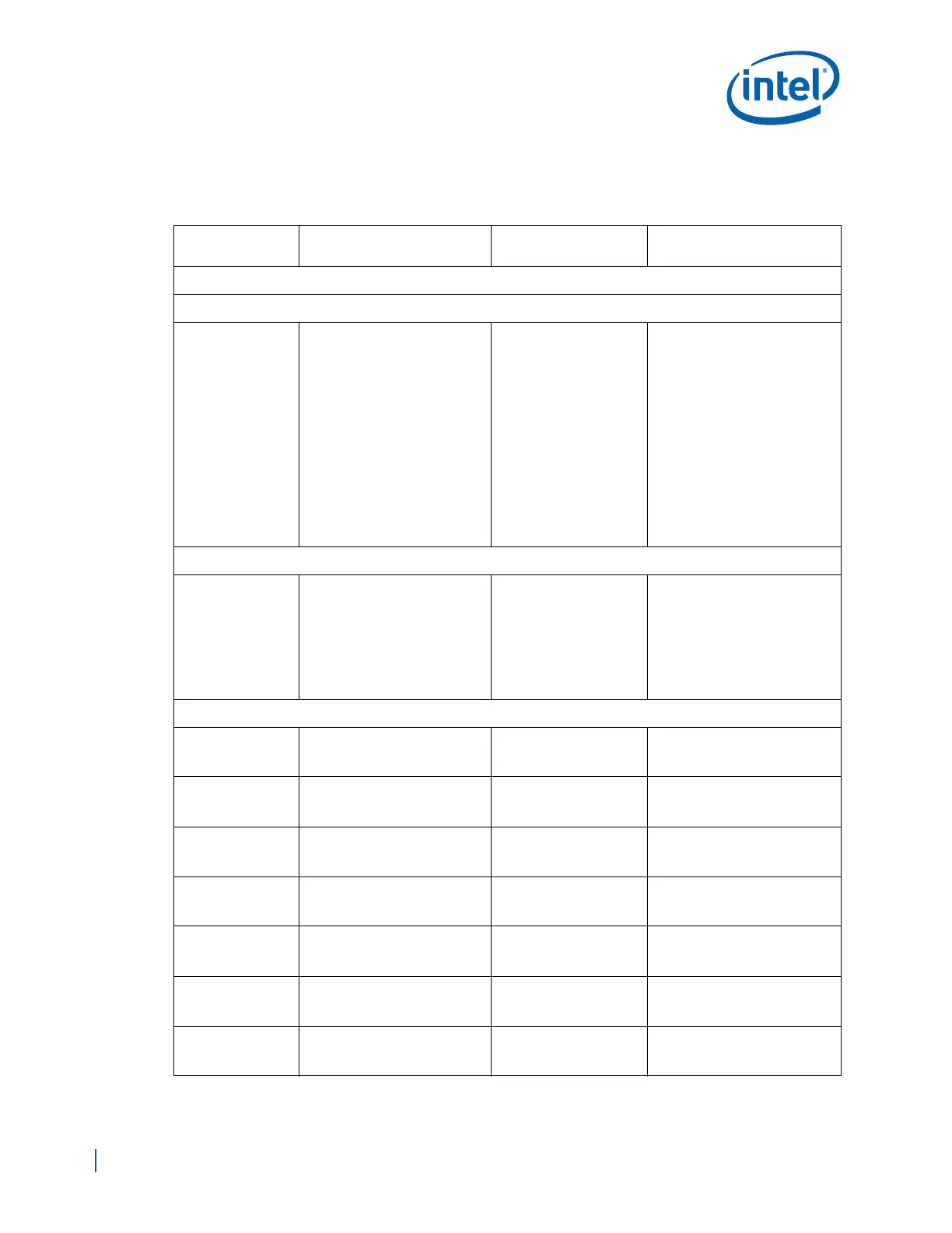
Table 97. Layout Checklist (Sheet 1 of 13)
Signal Name
Trace Geometry and
Impedance
Length Requirements Comments
IA-32 core Interface
Global Clock Unit (CRU)
CLKP100/CLKN100
or
BCLKP/BCLKN
Zdiff = 100
Ω +/- 10%
Trace Width – W
Brakeout Trace Width 4 mils
Microstrip: 4 mils
Stripline: 3.75 mils(L3/L8)
Stripline: 4.25 mils(L5/L6)
Brakeout Trace Width 4 mils
Airgap Spacing:
Brakeout spacing Min=4mils
Microstrip: 6 mils
Stripline: 9 mils
Spacing between Pairs 20mils
Spacing to other signals 20 mils
Serpentine Spacing 20 mils
Routing Length LT:
Min = 1 in.
Max = 10 in.
Inter-Pair length
matching: +/- 5 mils
See Section 8.2.1.1, “HOST_CLK
Topology”.
Thermal Diode
THERMDA
THERMDC
Recommended Trace Width:
Trace width = 10 mils.
Spacing to other signals 1 X
trace width.
Remote sensor should place as
close as possible to THERMDA
and THERMDC, approximately 4
to 8” away from the noise
sources.
Route the THERMDA and
THERMDC lines parallel and close
together with ground guards
enclosing them.
Sideband Miscellaneous Signals
CPUSLP_OUT#
Zo = 50
Ω +/- 10%
Spacing to other signals 3 X
trace width.
INIT33V_OUT#
Zo = 50
Ω +/- 10%
Spacing to other signals 3 X
trace width.
NMI
Zo = 50
Ω +/- 10%
Spacing to other signals 3 X
trace width.
SMI_OUT#
Zo = 50
Ω +/- 10%
Spacing to other signals 3 X
trace width.
STPCLK_OUT#
Zo = 50
Ω +/- 10%
Spacing to other signals 3 X
trace width.
RCIN#
Zo = 50
Ω +/- 10%
Spacing to other signals 3 X
trace width.
A20GATE
Zo = 50
Ω +/- 10%
Spacing to other signals 3 X
trace width.

 Loading...


