Intel
®
EP80579 Integrated Processor Product Line May 2010
Order Number: 320068-005US 130
System Memory Interface (DIMM)—Intel
®
EP80579 Integrated Processor Product Line
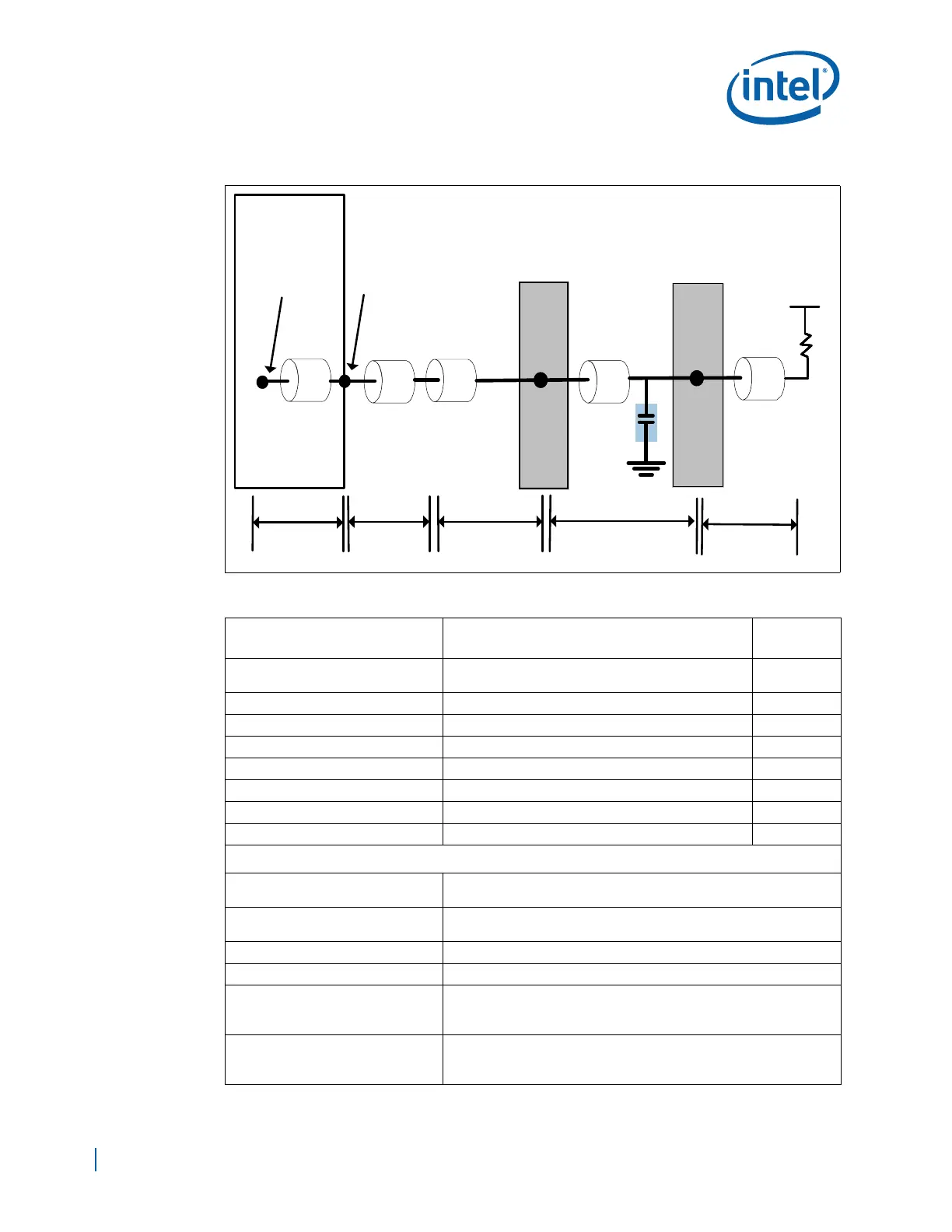
Figure 82. Address/Command Daisy Chain With Parallel Termination Topology Diagram
Table 46. DDR2 Address/Command Signal Group Routing Guidelines (Sheet 1 of 2)
Parameter
Routing Guidelines for 2-DIMM Solution with
ODT
Figure
Signal Group
DDR_MA[14:0], DDR_BA[2:0], DDR_RAS#,
DDR_CAS#, DDR_WE#
Topology Daisy Chain Figure 76
Reference Plane Ground Referenced
Layer Assignment Layers 3/8
Characteristic Trace Impedance (Zo) 40 Ω ±10% Figure 82
Nominal Trace Width 6.5 mils Figure 82
Nominal Trace Spacing (e2e) 15 mils Figure 82
Clearance from other signals 20 mils (min)
Board Routing Guidelines
Total Trace Length (TTL) = (L
PKG
+
L
BREAK
+ L
ROUTE
+ L
D2D
+ L
TERM
)
2.0 in - 6.0 in
L
PKG
See the Intel
®
EP80579 Integrated Processor Product Line Datasheet
for package length information.
L
BREAK
Max = 0.8 in
L
ROUTE
Max = 4.0 in
L
D2D
Max = 0.8 in
• Trace length skews for the control signal for DIMM-to-DIMM
routing should not exceed 10 mils
L
TERM
Max = 500 mils
• Trace length skews for the ADD/CMD signals to the termination
resistors (L
TERM
) should not exceed 200 mils.
DIMM 0
DIMM 1
EP80579
D
EP80579
Pin
Breakout
Routing
Dimm2Dimm
Routing
Package
Trace
EP80579
Pad
Board
Routing
A
B
C
L
PKG
L
BREAK
L
ROUTE
L
D2D
E
VTT_DDR
L
TERM
Ccomp
Rtt