Intel
®
EP80579 Integrated Processor Product Line—Platform System Clock
Intel
®
EP80579 Integrated Processor Product Line
Platform Design Guide May 2010
103 Order Number: 320068-005US
Note: These clocks are asynchronous to any other clock on the board.
8.3 CK410 General Design Guides
8.3.1 Clock Driver Decoupling
• For all power connection to planes, decoupling caps and vias, the maximum trace
width allowable and shortest possible lengths should be used to ensure lowest
possible inductance.
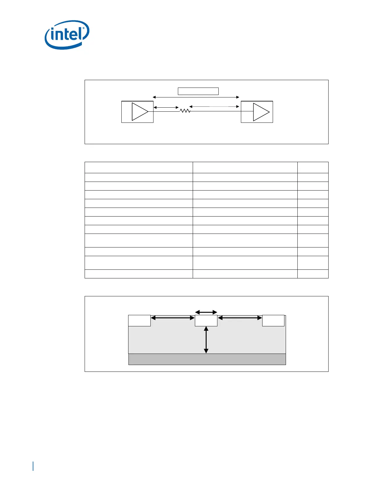
Figure 64. Topology for CLK48 Group
Table 24. CLK48 Routing Guidelines
Parameter Routing Guidelines Figure
Signal Group CKL48 USB
Reference Plane Ground Referenced
Layer Assignment Layer 3
Characteristic Trace Impedance (Zo) 50 Ω ±10% (single ended)
Nominal Trace Width (W) 4.5 mils Figure 65
Nominal Trace Spacing (S1) 20 mils Figure 65
Routing Length – L1: Clock Driver to Rs 0.5 in. max Figure 64
Routing Length – L2: Rs to Device Down or
Connector
2in. to 20in. max Figure 64
Resistor Rs = 43 Ω
±5% Figure 64
Skew Requirements (to other clock groups) None – USBCLK is asynchronous to other
clocks on the board
Figure 64
Maximum via Count 2
Figure 65. Trace Spacing for CLK48 (USBCLK) Clocks
L1
L2
Clock
Driver
Rs
EP80579
LT=L1+L2