Intel
®
EP80579 Integrated Processor Product Line—Real Time Clock (RTC) Interface
Intel
®
EP80579 Integrated Processor Product Line
Platform Design Guide May 2010
197 Order Number: 320068-005US
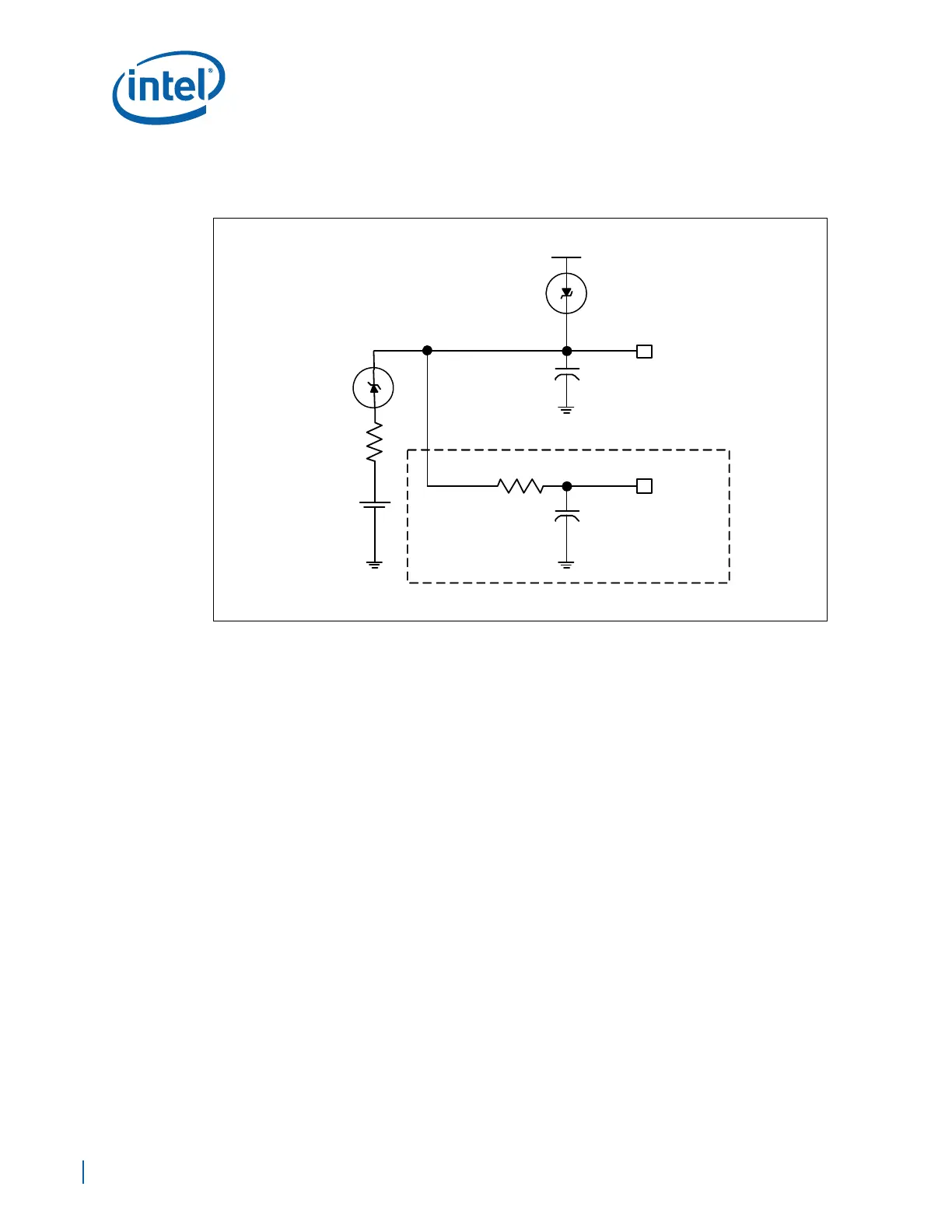
15.1.5 Internal only RTC External RTEST# Circuit
The RTC requires some additional external circuitry. The RTEST# signal is used to reset
the RTC well. The external capacitor and the external resistor between RTEST# and the
RTC battery (VBAT) were selected to create an RC time delay, such that RTEST# will go
high some time after the battery voltage is valid. The RC time delay must be in the
range of 18–25 ms. When RTEST# is asserted, bit 2 (RTC_PWR_STS) in the
GEN_PMCON_3 (General PM Configuration 3) register is set to 1 and remains set until
software clears it. As a result of this, when the system boots, the BIOS knows that the
RTC battery has been removed.
The RTEST# signal may also be used to detect a low battery voltage. RTEST# will be
asserted during a power up from the G3 state if the battery voltage is below 2V. This
will set the RTC_PWR_STS bit as described above. If desired, BIOS may request that
the user replace the battery.
This RTEST# circuit is combined with the diode circuit (shown in Figure 131), whose
purpose is to allow the RTC well to be powered by the battery when the system power
is not available. Figure 132 is an example of this circuitry that is used in conjunction
with the external diode circuit.
15.1.6 SUSCLK
SUSCLK is a square waveform signal output from the RTC oscillation circuit. Depending
on the quality of the oscillation signal on RTCX1 (largest voltage swing), the SUSCLK
duty cycle can be between 30%–70%. If the SUSCLK duty cycle is beyond the 30%–
70% range, it indicates a poor oscillation signal on RTCX1 and RTCX2.
SUSCLK can be probed directly using a normal probe (50 Ω input impedance probe)
and is an appropriate signal to check the RTC frequency to determine the accuracy of
the RTC Clock.
Figure 132. RTEST# External Circuit for the RTC
VCCPSUS
VCCPRTC
1.0 μF
20 kΩ
RTEST#
RTC
RTEST#
Circuit
DIODE/
BATTERY
CIRCUIT
1.0 μF
1 kΩ
+