Intel
®
EP80579 Integrated Processor Product Line—Local Expansion Bus (LEB) Interface
Intel
®
EP80579 Integrated Processor Product Line
Platform Design Guide May 2010
241 Order Number: 320068-005US
22.3.2.1 Chip Select Address Allocation
The LEB occupies 256 MB of address space in the EP80579 Memory Map. Each of the
eight chip selects in the LEB has been allocated 32 MB of addressing space which can
be individually programmed through the Timing and Control register. For a complete
description of the chip select functionality, see the Local Expansion Bus Controller in the
Intel
®
EP80579 Integrated Processor Product Line Datasheet.
22.3.3 Address Star Topologies
Address signals are normally routed in a multi-point topology; the main reason for this
is due to the nature of the bus. The bus is meant to interface with multiple devices
which interconnect in a parallel fashion; usually there being more than one device,
connected to the interface. The group signals are required to be matched with each
other, a conservative matching value could be within 500 mils. The matching number
will go down as the speed of the bus is increased. Each of the address, data, chip
selects and control signal groups must also match with each other. Attempt to math the
signals as close as possible. This will help avoid potential timing issues. Notice that for
the address signals, it is not required to use dumping series resistors. However
depending on your design configuration, it might be required to place pull-down
resistors for strapping purpose at boot time. Make sure proper pull-down resistors are
in place for you system configuration. It is recommended to use 1K ohm pull-down
resistor. Pull-ups are not required, as there is an internal weak resistor already that
pulls the signal high.
Figure 148 shows the star topology used in the Development Board design to
interconnect the data bus to the various peripherals in the LEB bus. Table 90 provides
the general routing rules such as impedance, min and max trace lengths.
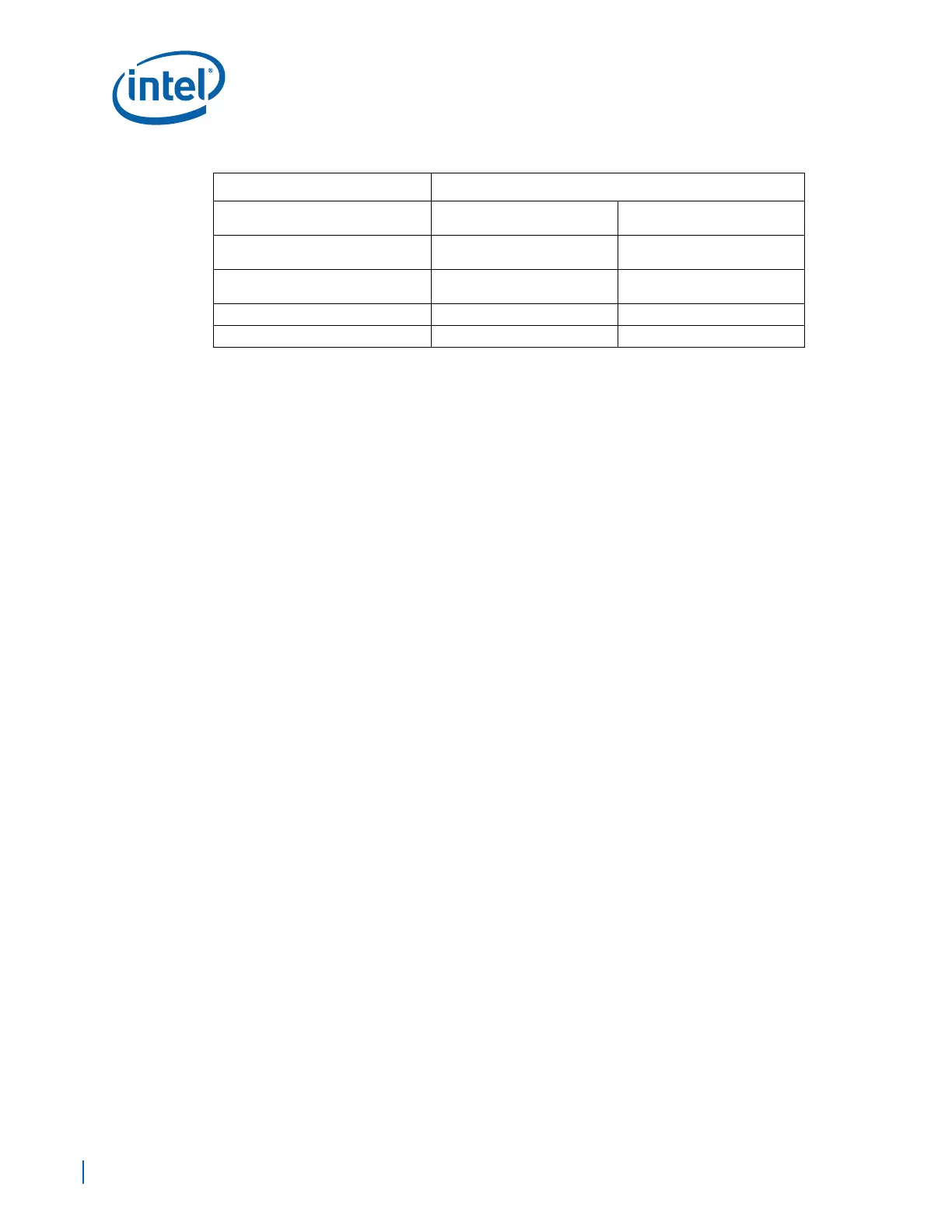
EP80579 Chip Select Breakout Length
(LCS_Brk_out)
1 inch (max) 1 inch (max)
Chip Select Board Length
(LCS_Brd_route)
max = 16 inch max = 16 inch
EP80579 Chip Select Breakin Length
(LCS_Brk_in)
1.5 inch (max) 1.5 inch (max)
Pull Up Resistor (Rpull_up) 10 KΩ (5%)) 10 KΩ (5%)
Breakout\Breakin Spacing (e2e) 4 mils (min) 4 mils (min)
Table 89. Chip Select Point-to-Point Topology Routing Guidelines (Sheet 2 of 2)
Parameter Routing Constraints