Intel
®
EP80579 Integrated Processor Product Line May 2010
Order Number: 320068-005US 43
High-Speed Design Concerns—Intel
®
EP80579 Integrated Processor Product Line
5.4.1 Serpentine Line Rules for Differential Signals
A meander or serpentine line is a transmission line routed in such a manner that
segments of the line zigzag and couple to the other segments of the same line. To
achieve balanced trace lengths for the critical signals within a group or between the
groups, the meander lines can be used to provide fine control of the delay skew
requirements. Because of the difference in delays between a straight line and a
serpentine line with tight pitch, design rules are needed to guarantee the proper delay
skew control for the serpentine lines. When routing matched length lines, the
serpentine traces must be at least 100 mils long and 30 mils apart. Meander or
serpentine shapes are responsible for a significant reduction in the propagation delay,
as compared to the delay in a straight line, as a result of the crosstalk between parallel
sections of the serpentine line.
• A sufficient rule of thumb: the edge-to-edge separation of the serpentine line to
any other trace must be at least 3x the separation trace width in the stripline
structure and 5x when routing in the microstrip structure so that crosstalk is
minimal.
• Limit the total number of turns to 15 or fewer for the serpentine traces.
• If the layout permits, make the turns larger and fewer.
• Maintain the spacing, preferably > 10x, both within a meander and between a
meander and the other signals.
• Any miter turn must not be greater than 45°.
• No sharp corner or 90° bend is allowed.
5.4.2 Stitching Differential Signals Between Layers
Differential signals must not pass over plane splits if possible. If absolutely necessary,
the planes must be stitched together with capacitors where the differential signals
cross the plane splits. If such stitching is impractical, the impact is primarily on EMI,
not on the signal integrity of the differential signal. If the routing goes from one side to
another, vias can be used for multiple signals. Some basic rules when stitching planes
together are as follows:
• The signal of a pair may pass through a single reference plane without stitching.
• Vias are presumed to be through-hole. The layers the signal current traverses, not
the layers the via traverses, should be considered more important. Use stitching
vias when a signal passes through more than one reference plane.
• If the planes are at the same potential, both ground, they must be directly tied
together.
• When the stitching vias are used where a signal changes layers, they must be
symmetrically placed within ~125 mils of the signal vias. See Figure 13.
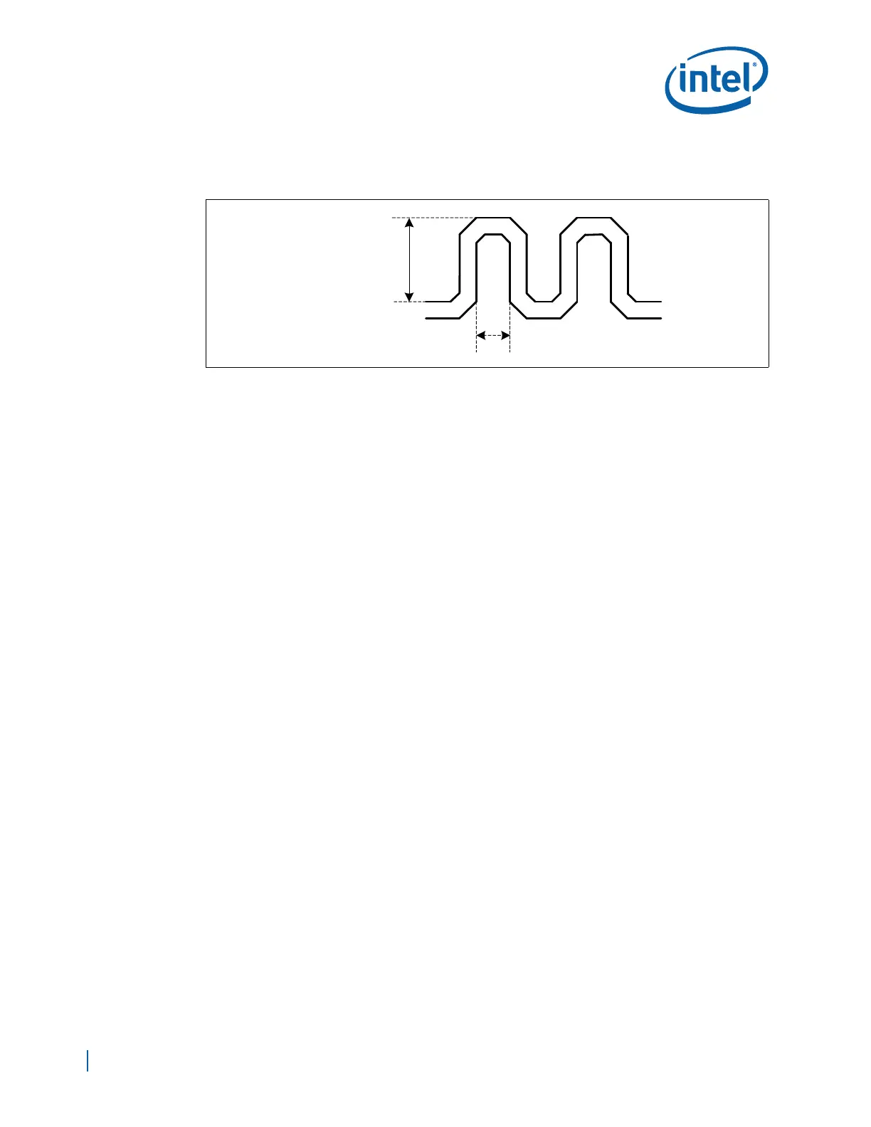
Figure 10. Serpentine Line
Minimum Serpentine
Length = 100 mils
Minimum Serpentine
Width = 30 mils