Intel
®
EP80579 Integrated Processor Product Line May 2010
Order Number: 320068-005US 87
Power Management and Reset Interface—Intel
®
EP80579 Integrated Processor Product Line
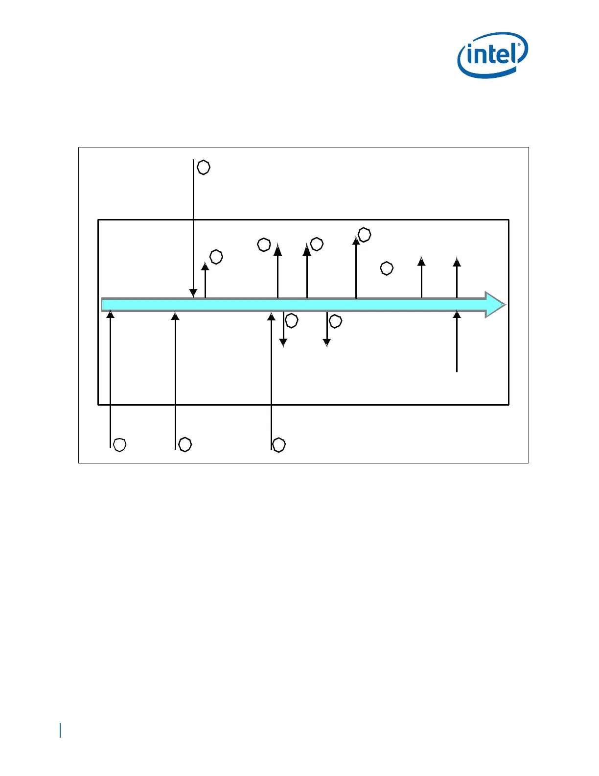
7.2.3 Reset Sequence
Figure 50 shows the reset sequence executed by EP80579 during power up.
7.2.3.1 Reset Procedure
1. EP80579 receives power and drives its BSEL and V_SEL pins. IA-32 core
VRMPWRGD, and SYS_PWR_OK are not asserted. PLTRST# (platform signal) and
CPURST# (internal signal) are asserted.
2. VRMPWRGD is asserted (platform signal).
3. Reference Clock provided from platform is stabilized. Voltage regulator output is
modified to correspond to BSEL and V_SEL values.
4. CRU PLL locks.
5. SYS_PWR_OK (platform signal) == PWROK/PWRGD internal signal asserted.
6. IO and PLLs are locked to achieve stable IA-32 core Clocking.
7. IICH de-asserts PLTRST#.
8. All EP80579 blocks except the IA-32 core come out of reset.
9. IMCH de-asserts CPURST#.
Figure 50. Reset Sequence
1
4
5
6
7
8
10
Power Applied
to EP80579
Reference Clock Stable
(from clock generator)
PWROK
PWRGD
SYS_PWR_OK
CPU_VRM_PWR_GD
(from platform)
CRU
Clock
Stable
PLTRST#
de-asserted
All the blocks
CPURST#
de-asserted
Reset
Microcode
Execution
Re-steer
to BIOS
M-unit
Initialization
DDR2
Initialization
IICH IMCH
CPU
EP80579
IMCH
2
(from platform)
VRMPWRGD
5
IICH
CPUPWRGD
asserted
CPU
FSB and
Core
Clocks
Stable
9
3
except the IA-32 core
come out of reset