Intel
®
EP80579 Integrated Processor Product Line—System Memory Interface (SODIMM)
Intel
®
EP80579 Integrated Processor Product Line
Platform Design Guide May 2010
328 Order Number: 320068-005US
Resistor packs are acceptable for the parallel (R
TT
) address/command termination
resistors, but address/command signals cannot be routed to the same resistor pack
(RPACK) used by data, data strobe, or control signals.
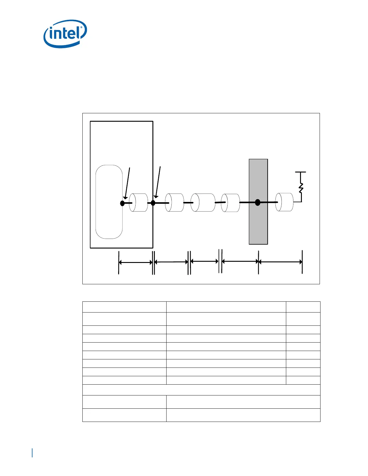
Figure A-5, and Table A-12 show the recommended topology and layout routing
guidelines for the DDR2-SDRAM address/command signals. Do not change layers. Place
the parallel termination resistors close to the SODIMM.
Figure A-5. Address/Command With Parallel Termination Topology Diagram
Table A-12. DDR2 Address/Command Signal Group Routing Guidelines (Sheet 1 of 2)
Parameter Routing Guidelines for SODIMM Figure
Signal Group
DDR_MA[14:0], DDR_BA[2:0], DDR_RAS#,
DDR_CAS#, DDR_WE#
Topology Point-to-Point
Reference Plane Ground Referenced
Layer Assignment Layers 3/8
Characteristic Trace Impedance (Zo) 40 Ω ±10% Figure A-5
Nominal Trace Width 6.5 mils Figure A-5
Nominal Trace Spacing (e2e) 3X Trace Width Figure A-5
Clearance from other signals 20 mils (min)
Board Routing Guidelines
Total Trace Length (TTL) = (L
PKG
+
L
BREAKOUT
+ L
ROUTE
+ L
BREAKIN
)
1.0 in - 4.5 in
L
PKG
See the Intel
®
EP80579 Integrated Processor Product Line Datasheet
for package length information.
E
Rtt
VTT_DDR
L
TERM
SODIMM
EP80579
D
EP80579
Die
EP80579
Pin
Breakout
Routing
Breakin
Routing
Package
Trace
EP80579
Pin
Board
Routing
ABC
L
PKG
L
BREAKOUT
L
ROUTE
L
BREAKIN