Intel
®
EP80579 Integrated Processor Product Line—Schematics Checklist
Intel
®
EP80579 Integrated Processor Product Line
Platform Design Guide May 2010
283 Order Number: 320068-005US
28.0 Schematics Checklist
The schematic checklist provides design recommendations and guidance for the
development of EP80579-based platform designs. See the individual peripheral
interface chapters in this document for further details.
Note: Some of the information in this document may not be applicable if a customer design
implementation deviates from what was implemented in the Development Board.
28.1 Functional Signal Definitions
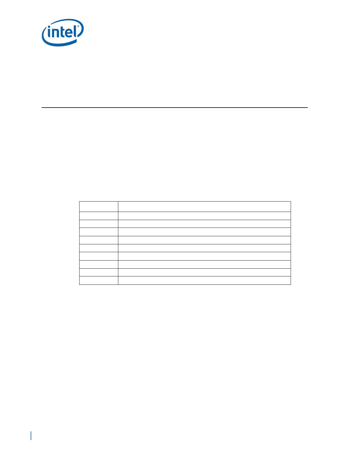
Table 99 provides the legend for interpreting the I/O Type field that appears throughout
the tables in this section.
Table 99. Signal Type Definitions
Symbol Description
# Active low signal
I Input pin only
O Output pin only
I/O Pin can be either an input or output
OD Open Drain pin
PWR Power pin
GND Ground pin
Reserved Pin must be connected as described, where n is the reserved pin number
NCn No Connection, where n is the NC pin number