Intel
®
EP80579 Integrated Processor Product Line—System Management Bus (SMBus)
Interface
Intel
®
EP80579 Integrated Processor Product Line
Platform Design Guide May 2010
180 Order Number: 320068-005US
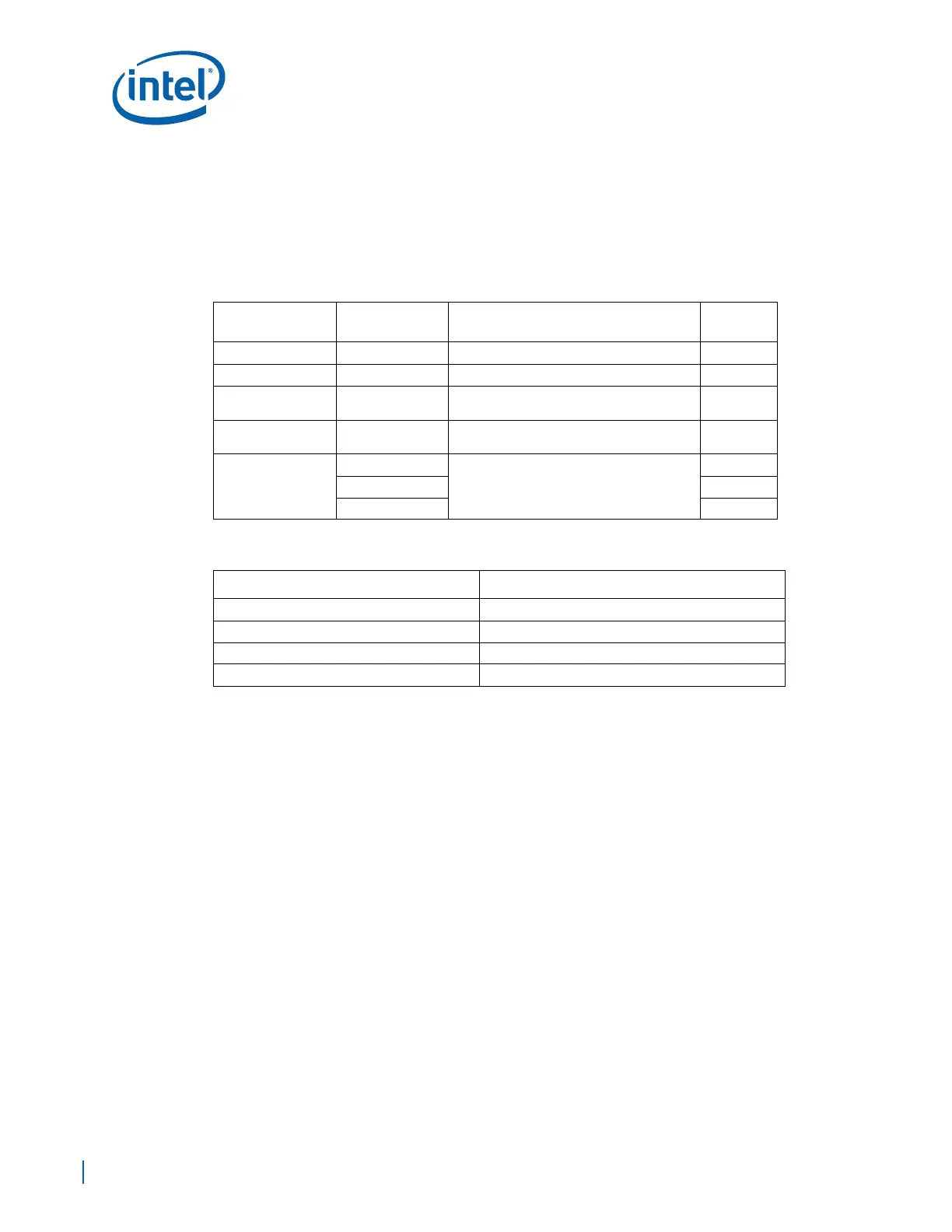
13.1.4 Calculating the Physical Segment Pull-Up Resistor
The following tables are provided as a reference for calculating the value of the pull-up
resistor that may be used for a physical bus segment. If any physical bus segment
exceeds 400 pF, a bus bridge device similar to the Phillips PCA9515 must be used to
separate the physical segment into two segments that individually have a bus
capacitance less than 400 pF.
13.2 Enabled System Management Features (Optional)
System management features for EP80579 allow a system platform to administer and
monitor the system, such as processor temperature monitoring, power failure, etc.
System management feature can be implemented by using a separate controller
commonly referred to as a bus management controller (BMC), See Table 69. The
Development Board does not support this feature. This feature can be custom design to
consider add the BMC connector for an add in the BMC card. Intel did not validate this
solution on the Development Board.
A list of system management features appears below
Note: Most of these features are theoretical implementations, they are not presented in the
Development Board implementation and have not been simulated.
• Monitor processor temperature
The processor has a thermal diode connected to the THERMDA and THERMDC pins.
The LM93 uses its A/D converter to determine the processor temperature. When
the processor temperature reaches its threshold, the system management sends
an alert to the administrator.
• Adjust processor temperature
Power consumption can be adjusted by controlling the PWM fan speed. The system
management can adjust the fan speed depending on the processor temperature. If
Table 67. Bus Capacitance Reference Chart
Device
No. of Devices/
Trace Length
Capacitance Includes Cap (pF)
EP80579 1 Pin Capacitance 12
CK410 1 Pin Capacitance 10
DIMMs 2
Pin Capacitance (5 pF) + 4” worth of trace
capacitance (2 pF/inch)
28
PCI Express Slots 2
Each add-in card is allowed up to 40 pF + 3
pF per each connector
86
SMBus Trace Length
in inches
24
2 pF per inch of trace length
48
36 72
48 96
Table 68. Bus Capacitance/Pull-Up Resistor Relationship
Physical Bus Segment Capacitance Pull-Up Range (For Vcc = 3.3V)
0 to 100 pF 8.2 kΩ to 1.2 kΩ
100 pF to 200 pF 4.7 kΩ to 1.2 kΩ
200 pF to 300 pF 3.3 kΩ to 1.2 kΩ
300 pF to 400 pF 2.2 kΩ to 1.2 kΩ