Intel
®
EP80579 Integrated Processor Product Line—System Memory Interface (SODIMM)
Intel
®
EP80579 Integrated Processor Product Line
Platform Design Guide May 2010
332 Order Number: 320068-005US
Note: These decoupling recommendations are for the EP80579 pins. Place multiple capacitors
in parallel to get the desired value for capacitance and ESL.
A.6 Clock Delay Programming and Write Levelization
The EP80579 primary memory clocks CK[1:0]/CK[1:0]# have write levelization
circuitry, WDLL.
Because of difference in loading between CTRL signals and CMD/ADD signals, flight
time skew between these two signal groups could be substantial. This is more
pronounced in the case of raw cards E and F where Control signals have 8 SDRAM loads
respectively and CMD/ADD signals have 16 loads respectively.
Since both signals (CTRL and CMD) are latched on the same clock crossing, therefore
clock needs to be positioned as close as possible to the middle of both CTRL and CMD
valid windows. Positioning the clock into the optimal window is enabled by controlled
push out of clock WDLL.
The clock WDLL can be pushed out up to one clock cycle in a 32 incremental steps.
Because relative position of valid CTRL and Valid CMD center may vary depending on
memory speed and silicon and board skews, this value could be different for different
raw cards, and different speeds.
In the case where this is not possible, and CTRL requirement conflicts with CMD
requirement with respect to positioning the clock crossing point, priority goes to the
Ctrl signal, CMD signals are then switched to the 2T timing mode. The priority is
dictated by the architectural requirement that the Chip Select (CS#) has always to
toggle in 1T and can not be scaled down to 2T. In other words, we have to satisfy CS#
1T timing first, then try to tune the Clock WDLL to accommodate the CMD signals
whenever possible, or switch the CMD signals to 2T timing.
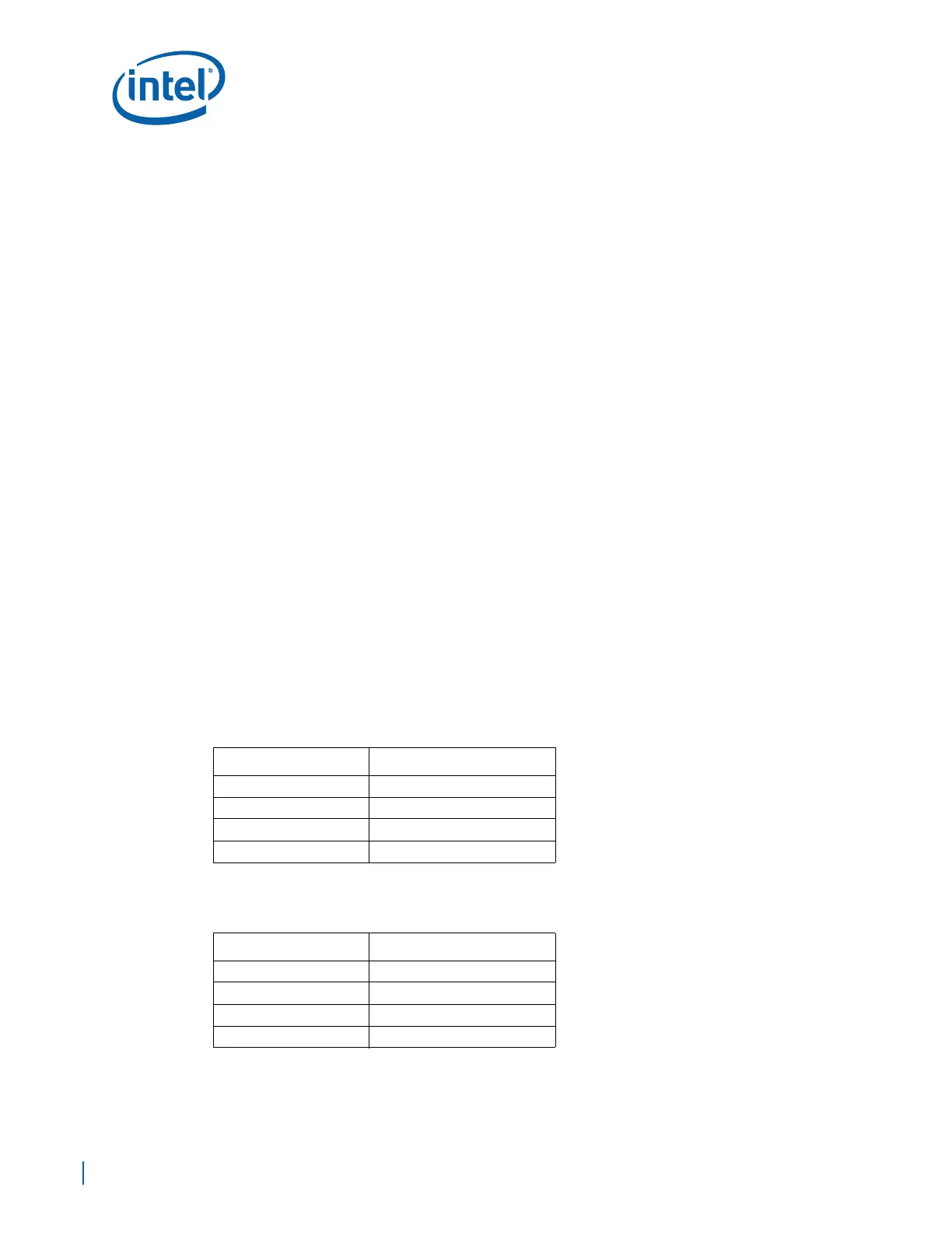
A.6.1 SODIMM Write Levelization Values
Table A-14 andTable A-15 provide the Write Levelization settings for single-rank and
dual-rank SODIMM modules.
Table A-14. Write Levelization for Single Rank Configuration
Data Rate Number of Clock Push Out
400 MT/s 20
533 MT/s 12
667 MT/s 11
800 MT/s 8
Table A-15. Write Levelization for Dual Rank Configuration
Data Rate Number of Clock Push Out
400 MT/s 7
533 MT/s 8
667 MT/s 13
800 MT/s 14