Intel
®
EP80579 Integrated Processor Product Line May 2010
Order Number: 320068-005US 207
Serial Interface Unit (SIU/UART)—Intel
®
EP80579 Integrated Processor Product Line
18.1.2 SIU Interface Interconnect
The High-Speed SIU interface can be configured to support speeds from 300 baud to
115 Kbaud. This interface supports five, six, seven, or eight data bit transfers, one or
two stop bits, as well as even-, odd-, or no-parity configurations.
Figure 134 illustrates how the SIU signals are connected to the RS-232 transceiver.
This RS-232 transceiver has five transmit and three receive signals to handle all
modem control signals. To ensure proper implementation, see the transceiver
component design guide for the Transceiver-to-DB9 Connector interface filter
requirements.
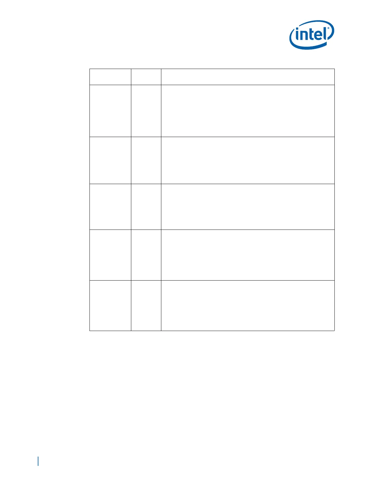
SIU_DSR[2:1]# I/O
DATA SET READY for UART1 and UART2: [Active low].
This pin indicates that the external agent is ready to communicate with UART.
These pins have no effect on the transmitter.
These pins could be used as Modem Status Input whose condition can be
tested by the processor.
Note:
• Must be pulled high through a 10 KΩ resistor when the port is not
connected to an interfacing device
SIU_DCD[2:1]# I/O
DATA CARRIER DETECT for UART1 and UART2: [Active low].
This pin indicates that data carrier has been detected by the external agent.
These pins are Modem Status Input whose condition can be tested by the
processor.
Note:
• Must be pulled high through a 10 KΩ resistor when the port is not
connected to an interfacing device
SIU_RI[2:1]# I/O
RING INDICATOR for UART1 and UART2: [Active low].
This pin indicates that a telephone ringing signal has been received by the
external agent. These pins are Modem Status Input whose condition can be
tested by the processor.
Note:
• Must be pulled high through a 10 KΩ resistor when the port is not
connected to an interfacing device
SIU_DTR[2:1]# I/O
DATA TERMINAL READY for UART1 and UART2:
When low these pins informs the modem or data set that UART 1, 2 are ready
to establish a communication link. The DTR#x(x=0,1) output signals can be
set to an active low by programming the DTRx (x-0,1) (bit0) of the Modem
control register to a logic 1. A Reset operation sets this signal to its inactive
state (logic 1). LOOP mode operation holds this signal in its inactive state.
Note:
• Can be left as NC when the port is not connected to an interfacing device
SIU_RTS[2:1]# I/O
REQUEST TO SEND for UART1 and UART2:
When low these pins informs the modem or data set that UART 1, 2 are ready
to establish a communication link. The RTS#x(x=0,1) output signals can be
set to an active low by programming the RTSx (x-0,1) (bit1) of the Modem
control register to a logic 1. A Reset operation sets this signal to its inactive
state (logic 1). LOOP mode operation holds this signal in its inactive state.
Note:
• Can be left as NC when the port is not connected to an interfacing device
Table 78. SIU Interface Signals (Sheet 2 of 2)
Signal Name
I/O
Direction
Description