Intel
®
EP80579 Integrated Processor Product Line May 2010
Order Number: 320068-005US 194
Real Time Clock (RTC) Interface—Intel
®
EP80579 Integrated Processor Product Line
15.1.2 External Capacitors
To maintain the RTC accuracy, the external capacitor values C1 and C2
must be chosen
to provide the manufacturer-specified load capacitance (C
load
) for the crystal when
combined with the parasitic capacitance of the trace, socket (if used), and package.
The following equation can be used to choose the external capacitance values:
where:
•C
load
= crystal’s load capacitance. This value can be obtained from the crystal
specification.
•C
in1
, C
in2
= input capacitances at the RTCX1 and RTCX2 signals of EP80579. These
values can be obtained from the Intel
®
EP80579 Integrated Processor Product Line
Datasheet.
•C
trace1
, C
trace2
= trace length capacitances measured from the crystal terminals to
the RTCX1 and RTCX2 signals. These values depend on the characteristics of board
material, the width of signal traces and the length of the traces. A typical value,
based on a 5 mils wide trace and a ½ ounce copper pour, is approximately equal to:
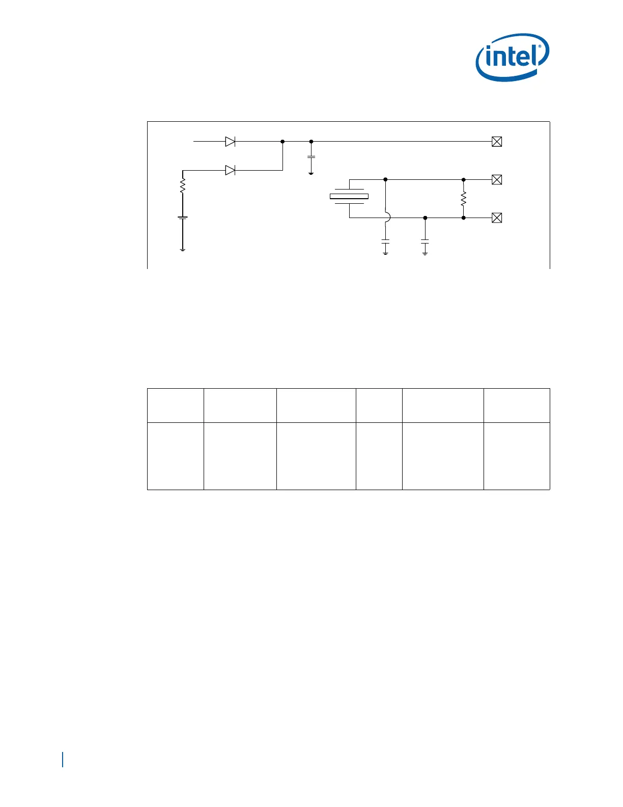
Figure 130. External Circuitry for the RTC
Notes:
1. The exact capacitor values for C1 and C2 must be based on the crystal maker recommendations.
Typical values for C1 and C2 are 15 pF, based on crystal load of 12.5 pF.
2. Reference designators are arbitrarily assigned.
3. VCCPSUS is active whenever the system is plugged in.
4. Vbatt is voltage provided by the battery.
5. VCCPRTC, RTCX1, and RTCX2 are EP80579 pins.
6. VCCPRTC powers the EP80579 RTC well.
7. RTCX1 is the input to the internal oscillator.
8. RTCX2 is the feedback for the external crystal.
Table 71. RTC Routing Summary
Trace
Impedance
RTC Routing
Requirements
Maximum Trace
Length To Crystal
Signal
Length
Matching
R1, C1, and C2
Tolerances
Signal
Referencing
50 Ω ±10%
5 mil trace width
(results in ~2 pF/
in.)
1.2 in. (the total
net length including
caps is 1.5 inches)
N/A
R1 = 10 MΩ ±5%
C1 = C2 = (NPO
class)
See Section 15.1.2
for calculating a
specific capacitance
value for C1 and C2
Ground
32.768 kHz
Xtal
10 MΩ
VCCPRTC
RTCX2
RTCX1
Vbatt
1μF
1 kΩ
VCCPSUS
C1
C2
R1
+
Schottky
Diodes
C
load
C
1
C
in1
C++
trace1
()C
2
C
in2
C
trace2
++()²[]C
1
C
in1
C
trace1
C
2
C
in2
C
trace2
++ +++[]⁄ C
parasitic
+=

 Loading...


