Intel
®
EP80579 Integrated Processor Product Line May 2010
Order Number: 320068-005US 235
Controller Area Network (CAN) Interface—Intel
®
EP80579 Integrated Processor Product Line
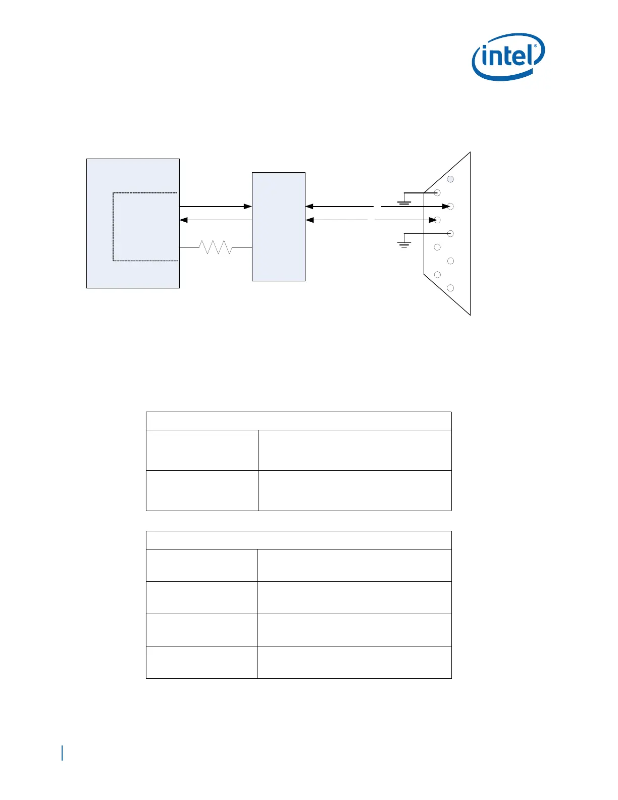
21.1 Input/Output Signal Application
The CAN controller has a total of three input/output signals per CAN port, as described
in the following tables.
All of the signals shown in the above two tables are single ended LVTTL 3.3V logic, and
they are NOT 5V tolerant.
Figure 144. CAN Physical Interface Example
DB9
Connector
CAN_TXD
CAN_RXD
CAN_TXEN_N
D
CAN
Transceiver
R
RS
CANH
CANL
1 RESERVE
2 CAN_L
3 CAN_GND
4 RESERVED
5 CAN_SHLD
6 GND
7 CAN_H
8 RESERVED
9 CAN_V+
1
6
2
7
3
8
4
9
5
EP80579
10K
to
100K
L1
L2
DIFFERENTIAL SIGNAL.
ROUTE SIGNALS FOR 120
DIFFERENTIAL IMPEDANCE.
L1 = L2
BXXXX-001
R1
CAN Interface
SN65HVD230
Inputs
CN0RXD
• Receive Data, Channel 0
• Must be tied high to a 10K ohm resistor when
the port is not connected to an interfacing
device.
CN1RXD
• Receive Data, Channel 1
• Must be tied high to a 10K ohm resistor when
the port is not connected to an interfacing
device.
Outputs
CN0TXD
• Transmit Data, Channel 0
• Can be left NC when the port is not connected
to an interfacing device.
CN1TXD
• Transmit Data, Channel 1
• Can be left NC when the port is not connected
to an interfacing device.
CN0TXEN
• Transmit Data Enable, Channel 0
• Can be left NC when the port is not connected
to an interfacing device.
CN1TXEN
• Transmit Data Enable, Channel 1
• Can be left NC when the port is not connected
to an interfacing device.