Intel
®
EP80579 Integrated Processor Product Line May 2010
Order Number: 320068-005US 41
High-Speed Design Concerns—Intel
®
EP80579 Integrated Processor Product Line
The inductance of the system caused by cables and power planes slows the power
supply's ability to respond quickly to a current transient. Decoupling a power plane may
be broken into several independent parts. More inductance is bypassed by placing the
capacitors closer to the load. Bypassing the inductance of leads, power planes, etc.,
requires less capacitance. However, trade-offs must be made since there is less room
for capacitance as it is placed closer to the load.
5.2.1 Bulk Decoupling
Larger bulk storage components, such as electrolytic capacitors, are placed across the
power input of the board to filter lower frequencies that usually are generated off the
board. A suitable capacitance value should be calculated, and many capacitors may be
placed in parallel to achieve the value. Maintaining voltage tolerance during changes in
current requires high-density bulk capacitors with low Effective Series Resistance
(ESR), and low Effective Series Inductance (ESL). Use thorough analysis when
choosing these components.
Power bypassing is required due to the relatively slow speed at which a DC-to-DC
converter may react. Bulk capacitance supplies energy from the time the high-
frequency decoupling capacitors are drained, until the power supply may react to the
demand. More correctly, the bulk capacitors in the system slow the transient
requirement seen by the power source to a rate it is able to supply, while the high-
frequency capacitors slow the transient requirement seen by the bulk capacitors to a
rate they may supply
5.2.2 High-Frequency Decoupling
The system boards should place high frequency decoupling as close to the power pins
and ground pins of the load as physically possible. Use both sides of the board when
necessary for placing load to achieve the optimum proximity to the power pins. This is
vital because the inductance of the board's metal plane layers could cancel the
usefulness of these low inductance components.
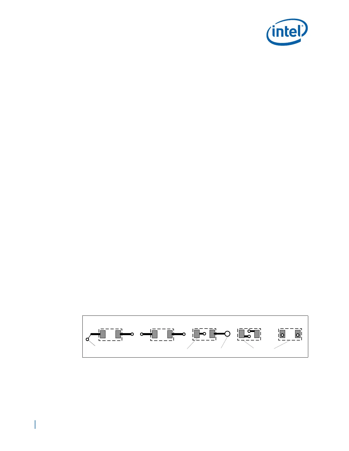
Shorten the path from the capacitor pads to the pins the capacitor is decoupling. When
possible, place the vias connecting to the planes within the pad of the capacitor. When
not possible, keep the traces as short and wide as is feasible. Possibly one or both ends
of the capacitor may be connected directly to the pins of the load without the use of a
via. Figure 7 illustrates these concepts.
Better performance can be obtained by minimizing the distance between the chip and
capacitor; the connection from the capacitor to the power pin should be kept as short
and wide as possible to minimize inductance of the connection. Consider placing the
capacitor on the opposite side of the board directly under the chip.
5.3 Serpentine Routing
A serpentine net is a transmission line, routed in such a manner that sections of the net
double back and couple to other segments of the same net (see Figure 8).
Figure 7. Proper Decoupling Capacitor Placement with Respect to Vias
Unacceptable
Via
Better
Pad
Capacitors
Good
Pin
Bad Optimal