Intel
®
EP80579 Integrated Processor Product Line May 2010
Order Number: 320068-005US 263
Debug Port Design Guide—Intel
®
EP80579 Integrated Processor Product Line
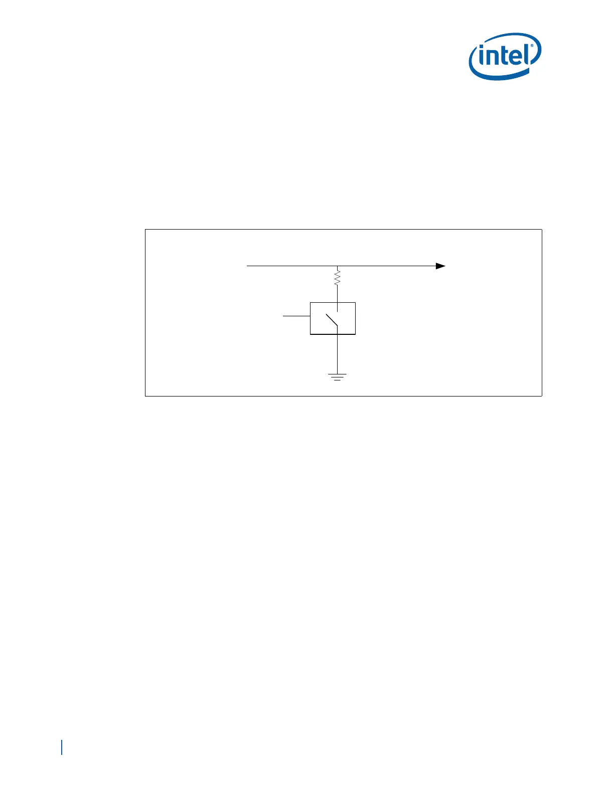
26.3.2.3 BPM5_PREQ_IN (BPM5) and BPM3_IN (BPM3) Routing Guidelines
These nets have a board level circuit required to shift the VOH of the signal from the
VCCOBS_AB/CD voltage level of 1.8V down to the 1.2V EP80579 core voltage of the
input buffer. Route point-to-point from the XDP debug port to a 100 ohm resistor on the
platform located within 1 inch of the EP80579 input pin. The other side of the 100 ohm
resistor is connected to an active LOW enable quickswitch such as the
SN75CBTLV1G125 or equivalent. When the quickswitch is enabled, the 100 ohm
resistor provides a path to GND. the quickswitch is controlled by the XDP_PRESENT#
signal described later in this document. There are no specific routing lengths required
for these nets.
26.3.3 Hook Pins Routing Guidelines
The Hook [7:0] pins are used by the ITP-XDP to manage the system power, scan, and
reset states of the target system. The pins are also used to support debug interfaces
that are not common to all platforms.
26.3.3.1 PWRGOOD (HOOK0) Routing Guidelines
Route a system PWRGOOD (CPUPWRGD pin) signal directly to the XDP HOOK0 pin. This
signal is used to indicate that the system’s power delivery subsystem has reached
stability. This signal must be asserted before the run-control tool will attempt
operations. The run-control tool will not drive PWRGOOD. The run-control tool will use
transitions on this signal as triggering events. Please consult the system’s Platform
Design Guidelines (PDG) for termination information. If edge integrity of PWRGOOD is
critical to the operation of the target system, it is acceptable to place a 1k ohm
isolation resistor, in series, between the target system PWRGOOD signal and the trace
to the XDP HOOK0 pin. If there is no PWRGOOD on the system, pull this signal up to a
voltage between 1.0V to 3.3V through a 1k to 10k ohm resistor.
There are no trace length requirements for this signal.
26.3.3.2 Reserved (HOOK[1])
This signal is reserved. No connection to this signal are required.
26.3.3.3 Reserved (HOOK[2])
This signal is reserved. No connection to this signal are required.
Figure 156. BPM5 and BPM3_in Platform Circuit
SN75CBTLV1G125
or Equivalent Active
Low Enable
QuickSwitch
100 ohms
XDP_PRESENT#
BPM5_PREQ_IN or
BPM3_IN Signal
XDP (Driver)
EP80579 (Receiver)