Intel
®
EP80579 Integrated Processor Product Line—Layout Checklist
Intel
®
EP80579 Integrated Processor Product Line
Platform Design Guide May 2010
270 Order Number: 320068-005US
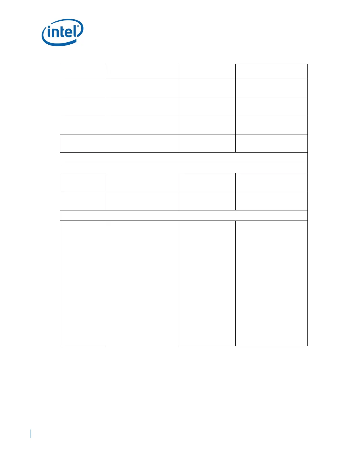
CPURST#
Zo = 50
Ω +/- 10%
Spacing to other signals 3 X
trace width.
CPUPWRGD_OUT
Zo = 50
Ω +/- 10%
Spacing to other signals 3 X
trace width.
BSEL
Zo = 50
Ω +/- 10%
Spacing to other signals 3 X
trace width.
V_SEL
Zo = 50
Ω +/- 10%
Spacing to other signals 3 X
trace width.
Integrated Memory Controller Hub (IMCH) Interface
IMCH Reset
RSTIN#
Zo = 50
Ω +/- 10%
Spacing to other signals 3 X
trace width.
PWRGD
Zo = 50
Ω +/- 10%
Spacing to other signals 3 X
trace width.
DDR2 SDRAM
DDR_DQ[63:0],
DDR_ECC[7:0],
DDR_DM[8:0],
DDR_DQS[8:0],
DDR_ DQS[8:0]#
Zo = 40 Ω +/- 10% single ended
Trace Width:
Brakeout Trace Width 4 mils
Stripline: 6.5 mils(L3/L8)
Airgap Spacing:
Brakeout spacing Min=4mils
DDR_DQ/DDR_ECC/DDR_DM
Min=15 mils
DDR_DQS to DDR_DQS# 6 mils
DDR_DQS Pair to Pair
Min=20mils
To any other signals Min=20mils
EP80579 to First DIMM
2.0 in to 4.0 in Max
First to Second DIMM
Max=0.8 in
Total Trace Length (TTL)
2.0 in - 6.0 in
DDR_DQS to DDR_DQS#
Match within 10 mils
Skew: Match all group
signals within 20 mils for
the same byte group. The
shortest signal of the
group must not exceed
the longest signal of the
byte group by 20 mils.
This requirement is for
the complete length from
EP80579 to the farthest
DIMM connector.
See Section 9.7, “DDR2 Interface
System Interconnect”.
Topology Daisy Chain
Reference Plane:
Ground and Power reference
plane
Route groups of signals on the
same layer from EP80579 to the
farthest DIMM.
No vias, except were required to
breakout.
Direct connection from EP80579
to each DIMM with no
termination.
Table 97. Layout Checklist (Sheet 2 of 13)
Signal Name
Trace Geometry and
Impedance
Length Requirements Comments

 Loading...


