NOTE: The control plane and the UDI must be on different subnets. If the control plane and UDI
are on the same subnet and assigned the same IP address, APs will be unable to communicate
with the control plane. If the control plane and UDI are on the same subnet and assigned different
IP addresses, hotspot clients will not be redirected to the logon URL for user authentication.
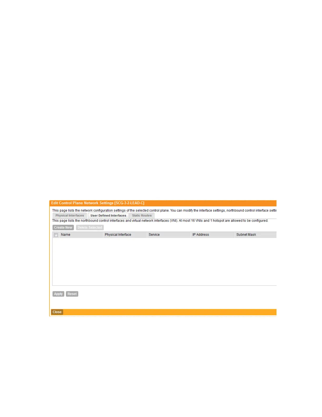
Follow these steps to configure the settings on the User Defined Interface tab.
1. Click the User Defined Interfaces tab.
2. Click the Create New button.
3. Configure the following interface settings:
a) Name: Enter a name for this interface.
b) IP Address: Enter an IP address to assign to this interface.
c) Subnet Mask: Enter a subnet mask for the IP address above.
d) Gateway: Enter the IP address of the gateway router.
e) VLAN: Enter the VLAN ID that you want to assign to this interface.
f) Physical Interface: Select either Control Interface or Management Interface.
g) Service: Select Hotspot or Not Specified.
4. Click Save.
5. Click Apply.
You have completed configuring the northbound portal interface settings.
Figure 115: The User Defined Interface tab
Static Routes Tab
To configure a static route, enter the destination IP address and related information for the
destination. You can also assign a metric (or priority) to help the controller determines the route
to choose when there are multiple routes to the same destination.
Follow these steps to configure a static route.
SmartCell Gateway 200/Virtual SmartZone High-Scale for Release 3.4.1 Administrator Guide
225
Configuring the System Settings
Configuring Cluster Planes