2-12 Phaser 6300/6350 Color Laser Printer Service Manual
2. Light Density Adjustment
At the execution of Automatic Density Control, the Light Density Adjustment is
made just before the toner patches for toner density control are generated.
Light is emitted from the LED using the current Light Density Setting, to check if the
output value of the CTD (ADC) Sensor is within the specified range. If the output
value is low, light density is increased. If the output value is high, light density is
decreased.
If the output value is less than the first lower limit, a warning message indicates the
sensor is dirty. If the output value is less than the second lower limit, a Fatal Error
signals that the sensor is faulty and the printer stops printing.
Color Registration Control
The printer uses a quad system where drums and developers are used exclusively for
each of the four colors (yellow, magenta, cyan, and black). Images are formed on the
drums, in the respective colors, and then layered to form one image. To avoid a
positional shift between the different color images, the color registration control
calculates how much the registration has shifted by comparing each of the other color
patches in the registration string to the black bar that precedes it. Shift is corrected by
adjusting the laser write timing to compensate.
Color registration control is made depending on the internal temperature and print
count at the execution of process control.
This control is outlined below:
1. With no toner on the Transfer Roller, the output value of the CTD (ADC) Sensor
is measured to determine the reference value.
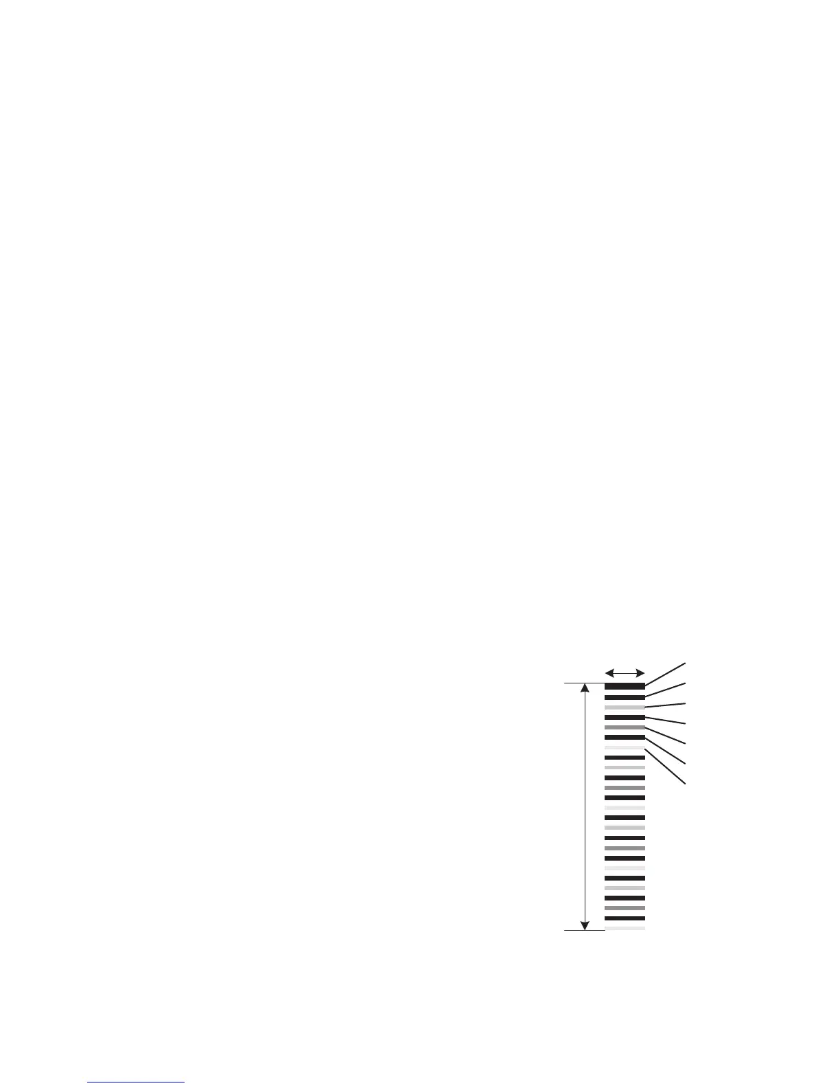
2. Patches for color registration control are
generated on the Transfer Roller. These
patches are composed of 10 mm lines of
each toner color in the following order: K,
C, K, M, K. The string of patches is led by a
black trigger patch that is larger than the
registration patches.
3. The density of patches generated is
measured by the CTD (ADC) Sensor.
4. The amount of registration shift is
calculated from the reference value
determined in Step 1 and the patch density
measured in Step 3.
5. The laser write timing is changed to
compensate for any registration shift.
10 mm
About One Turn
Of Transfer Roller
s6300-068
K
K
C
K
M
K
Y