Service Parts Disassembly 8-109
HVPS (PL9.1.21)
1. Remove the Top Main Cover (page 8-8).
2. Remove the Left Side Cover (page 8-13).
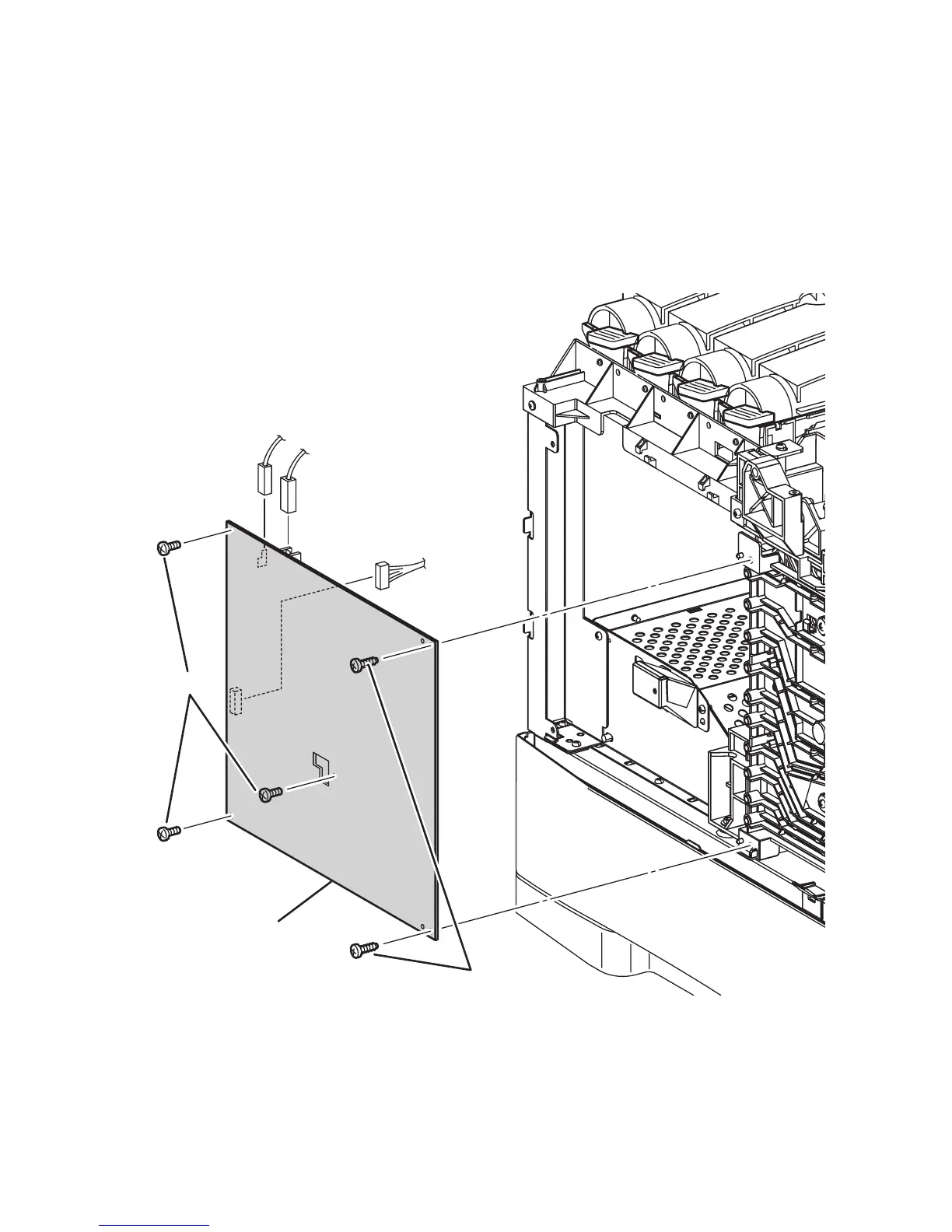
3. Unplug connectors P/J139, P/J140, P/J141.
4. From the left side of the printer remove the 2 screws (self-tapping, plastic 10
mm) and 3 screws (metal, 6 mm) that secure the HVPS to the frame.
5. Move the HVPS left to release the retaining hooks on the front edge of the board.
Replacement Note
Verify that the two bosses are aligned and the two retaining hooks are locked
on the board before tightening the mounting screws.
s6300-223
P/J140
P/J139
P/J141
HVPS
6 mm
10 mm