Service Parts Disassembly 8-61
Chute Assembly Out (PL5.3.1)
1. Remove the Top Main Cover (page 8-8).
2. Remove the Front Cover (page 8-10).
3. Remove the Right Front Cover (page 8-18).
4. Remove the Left Front Cover (page 8-18).
5. Remove the Right Side Cover (page 8-12).
6. Remove the Left Side Cover (page 8-13).
7. Remove Tray 1 (MPT) (page 8-39).
8. Remove the Tray 1 (MPT) Cover (page 8-40).
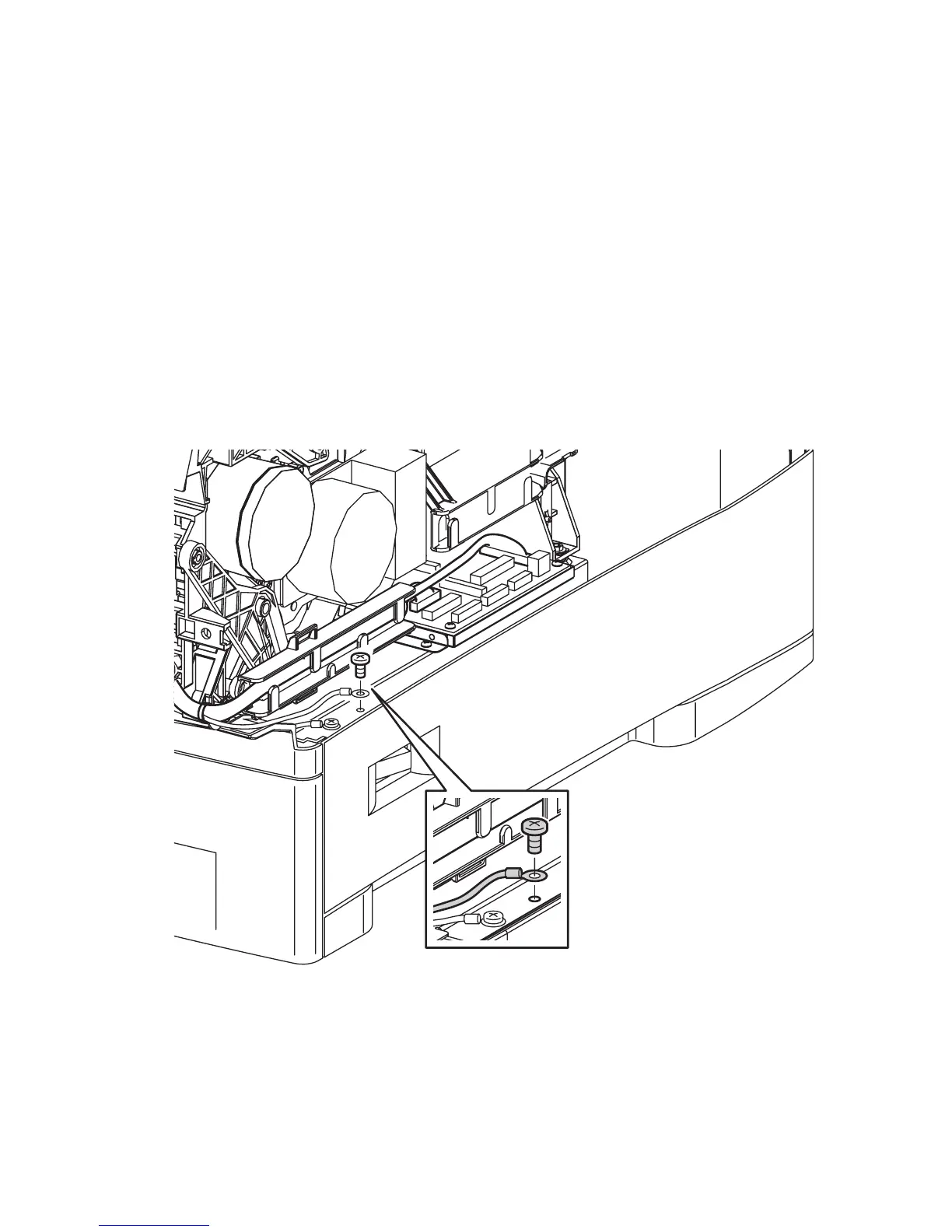
9. Remove the screw (metal with tooth washer, 5 mm) that secures the Tray 1 Feed
Solenoid ground wire to the right side of the bottom plate and remove the wire
from the Front Harness Guide.
10. Disconnect P/J710 (Imaging Unit CRUM connector), Developer Drive Assembly
(P/J491), and the Main Drive Assembly (P/J481) and remove the harnesses from
the cable guides.
s6300-189