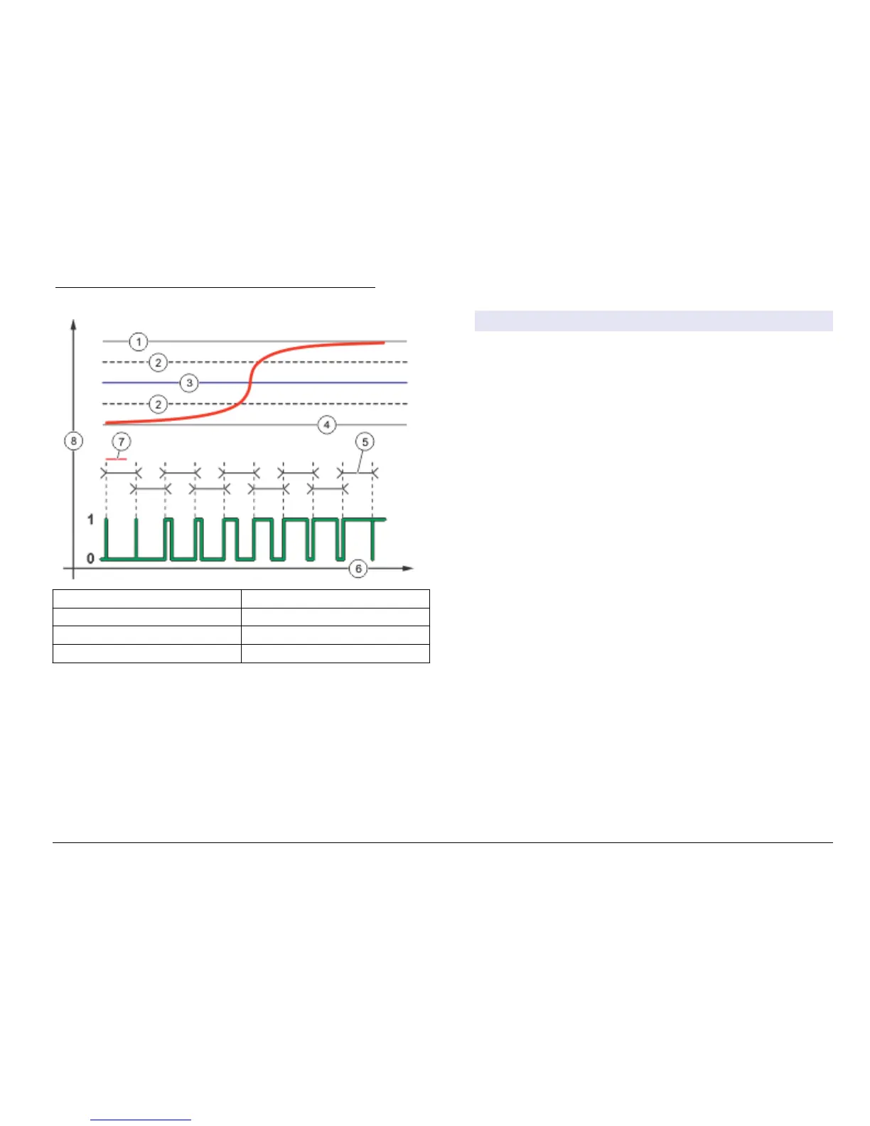
Figure 24 Pulse Width Modulation function (linear mode)
1 High alarm 5 Period
2 Deadband 6 Time (x-axis)
3 Setpoint 7 Phase
4 Low alarm 8 Selected source (y-axis)
• Frequency Control Function (refer to Figure 25)
Option Description
Set mode Auto—The relay works as a PID controller.
Manual—the signal is controlled by the user through manual
adjustment of the % change value. This option is shown as
Manual Output after the manual set mode is selected.
Phase Reverses the leading sign of the control deviation for the PID
controller (default: Reverse). The phase selects whether the
relay will operate at the first part of a cycle (direct phase) or
the second part (reverse phase).
Set setpoint Sets the process value which is controlled by the PID
controller.
Dead zone In this set range, the PID controller does not take action to
change the output frequency until within the limits of the dead
zone.
Pulse width Sets the cycle duration (0-600 seconds) of the PWM output
signal. (default: 0.5 seconds) The cycle duration is equal to
the duty cycle of the output signal.
Minimum
pulses
Sets the minimum number of pulses per minute at which the
relay can operate. Range: 0.001–4.000 (default: 1.000)
Maximum
pulses
Sets the maximum number of pulses per minute at which the
relay can operate. Range: 0.001–60.000 (default: 04.000).
This value cannot be set lower than Minimum Pulses value.
Prop band Sets the proportional part of the PID controller. The
proportional part of the controller supplies an output signal
which is linearly dependent to the control deviation. The
proportional part reacts on any changes at the input but starts
to oscillate easily if the value is set high. The proportional part
cannot fully compensate for disturbances.
Integral Sets the derivative part of the PID controller (default:
000 minutes). The integration part of the controller generates
an output signal. The output signal increases linearly if the
control deviation is constant. The integration part responds
slower than the proportional part and can fully compensate
disturbances. The higher the integration part, the slower it
responds. If the integration part is set too low, it starts to
oscillate.
(nglisK 35