22
User Interface and Navigation
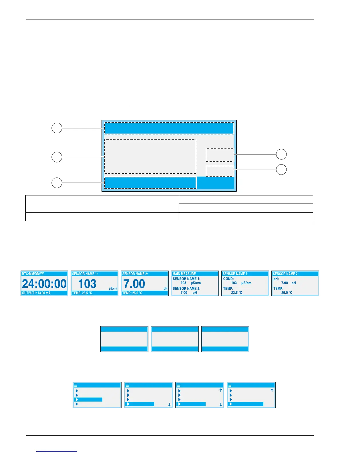
4.1.1 Controller Display Features
When a sensor is connected and the controller is in measurement mode, the controller
display will show the current conductivity reading plus the sample temperature.
The display will flash on startup, when a sensor error has occurred, when the hold outputs
function has been activated, and when a sensor is being calibrated.
An active system warning will cause the warning icon (a triangle with an exclamation point
inside) to be displayed on the right side of the display.
Figure 15 Display
4.1.2 Important Key Presses
• Press the HOME key then the RIGHT or LEFT key to display two readings when two
sensors are connected. Continue to press the
RIGHT or LEFT key to toggle through
the available display options as shown below.
• Press the
UP and DOWN keys to toggle the status bar at the bottom of the
measurement display to display the secondary measurement (temperature) and
output information.
• When in Menu mode, an arrow may appear on the right side of the display to indicate
that more menus are available. Press the
UP or DOWN key (corresponding to the
arrow direction) to display additional menus.
1. Status bar. Indicates the sensor name and status of relays.
The relay letter is displayed when the relay is energized.
30. Secondary measurement
31. Warning icon area
29. Main measurement 32. Measurement units (μS, mS, S, mohm, TDS)
103
1
2
3
5
4
μS/cm
SENSOR NAME
TEMP: 23.3 °C
SENSOR NAME SENSOR NAME SENSOR NAME
μS/cm
103
OUTPUT2: 11.25 mA
103
OUTPUT1: 13.00mA
μS/cmμS/cm
103
TEMP: 23.5 °C
SENSOR DIAG
SENSOR SETUP
TEST/MAINT
MAIN MENU
SYSTEM SETUP
OUTPUT SETUP
SYSTEM SETUP
NETWORK SETUP
RELAY SETUP
DISPLAY SETUP
DISPLAY SETUP
SYSTEM SETUP
LOG SETUP
SECURITY SETUP
CALCULATION
SECURITY SETUP
SYSTEM SETUP
CALCULATION
LOG SETUP
ERROR HOLD MODE