80459-641-01E Model 6 Motor Control Centers
10/2012 Section 4—Installing the MCC
© 1999–2012 Schneider Electric All Rights Reserved
51
ENGLISH
Cable Connection Torque Values The following tables provide main disconnect and branch feeder torque
values, which apply to both aluminum and copper conductors.
Component Instructional
Information
Component manuals for devices such as adjustable frequency drive
controllers, solid state reduced voltage starters, and programmable logic
controllers are included with the MCC instruction information packet.
Thermal overload selection data is listed on the inside of the vertical wire
trough door of each section. This information is also listed in this bulletin;
see “Thermal Overload Unit Selection” beginning on page 105. Select
proper thermal overloads from the applicable starter size tables.
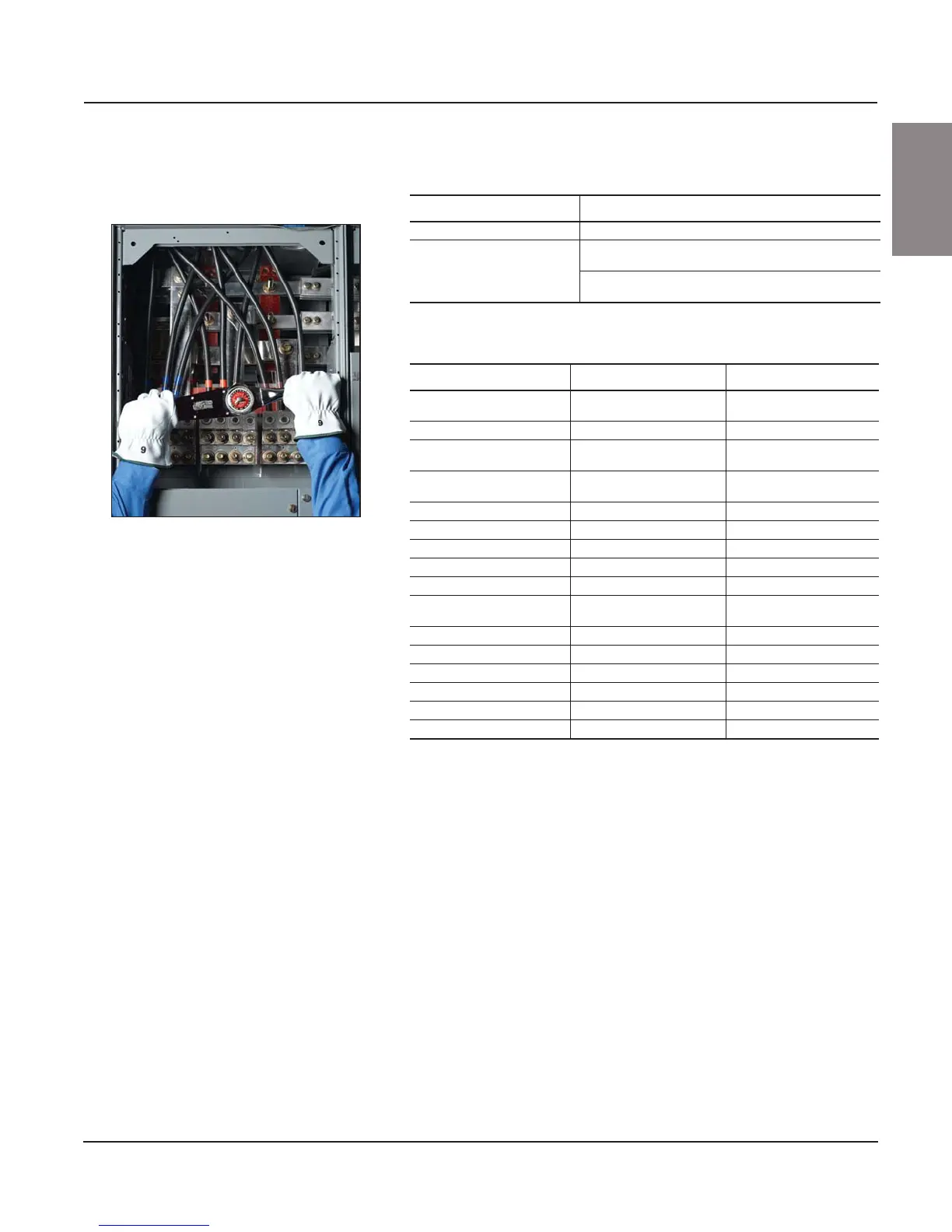
Figure 66: Main Lug Compartment Torque
Connection
Table 4: Connection Torque Values for Main Lug Compartments
1
1
See Figure 66.
Socket Size Across Flat Torque
3/8 in. 375 lb-in (42.4 N•m)
1/2 in.
500 lb-in (55.6 N•m)
for 800–1200 A, bottom main lug compartments
600 lb-in (67.8 N•m)
for all others
Table 5: Connection Torque Values for Main and Branch Feeders
Frame Size Ampere Rating Torque
H
15–30 A
35–150 A
50 lb-in (5.6 N•m)
120 lb-in (13.6 N•m)
J 150–250 A 225 lb-in (25.4 N•m)
FA
15–30 A
35–100 A
35 lb-in (3.9 N•m)
80 lb-in (9.0 N•m)
FC
20–30 A
40–100 A
35 lb-in (4.0 N•m)
65 lb-in (7.3 N•m)
KA 70–250 A 250 lb-in (28.2 N•m)
KC 110–250 A 250 lb-in (28.2 N•m)
LA/LH 125–400 A 200 lb-in (22.6 N•m)
LC/LI/LE/LX/LXI 300–600 A 300 lb-in (33.9 N•m)
LG/LH/LL/LR 300–600 A 442 lb-in (50 N•m)
MA/MH/ME/MX
200–400 A
450–1000 A
300 lb-in (33.9 N•m)
300 lb-in (33.9 N•m)
NT 400–1200 A 600 lb-in (67.8 N•m)
NW (top entry) 400–2500 A 600 lb-in (67.8 N•m)
PA/PH/PE/PX 800–2000 A 600 lb-in (67.8 N•m)
MJ/MG 300–800 A 450 lb-in (50.8 N•m)
PJ/PK/PG/PL 250–1200 A 450 lb-in (50.8 N•m)
RJ/RK/RG/RL 600–2500 A 500 lb-in (56.5 N•m)