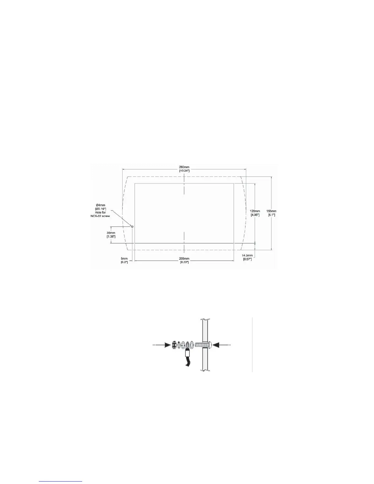
• See FIGURE 2-2 for cut-out dimensions.
2. If you are mounting the controller on a metal panel, earth the
power supply:
a Bore a hole (FIGURE 2-2) that suits the NC6-32 screw
supplied with the controller kit.
b. Scrape the panel paint away from the contact area to ensure a
conductive connection.
c. Drive the screw into the hole.
d. On the screw’s shank, place the following hardware in this
order: washer, ring cable shoe, second washer, spring, and
nut; as shown in FIGURE 2-3.
Figure 2-3. Earth Assembly
Figure 2-2. ModCon75 Controller Panel Cut-out—Front View
2-3