Digital Outputs
Wiring Power Supplies
1. Connect the "positive" lead to the:
• "V1" terminal for the relay outputs
• "V2" terminal for the transistor outputs.
2. In both cases, connect the "negative" lead to the "0V" terminal
for each output group.
• In the event of voltage fluctuations or non-conformity to voltage
power supply specifications, connect the device to a regulated
power supply.
• Do not connect the 'Neutral' or 'Line' signal of the 110/220 VAC
to the device’s 0V pin.
Relay Outputs
• The relay output 0-volt signal is isolated from the
controller 0-volt signal.
I0 Unlatch Zone 1 I6 Unlatch Zone
I1 Unlatch Zone 27 I7 Unlatch Zone 8
I2 Unlatch Zone 3 I8 Unlatch Zone 9
I3 Unlatch Zone 4 I11 Remote Sensor Acknowledge
I4 Unlatch Zone 5 I12 External Horn Silence
I5 Unlatch Zone 6
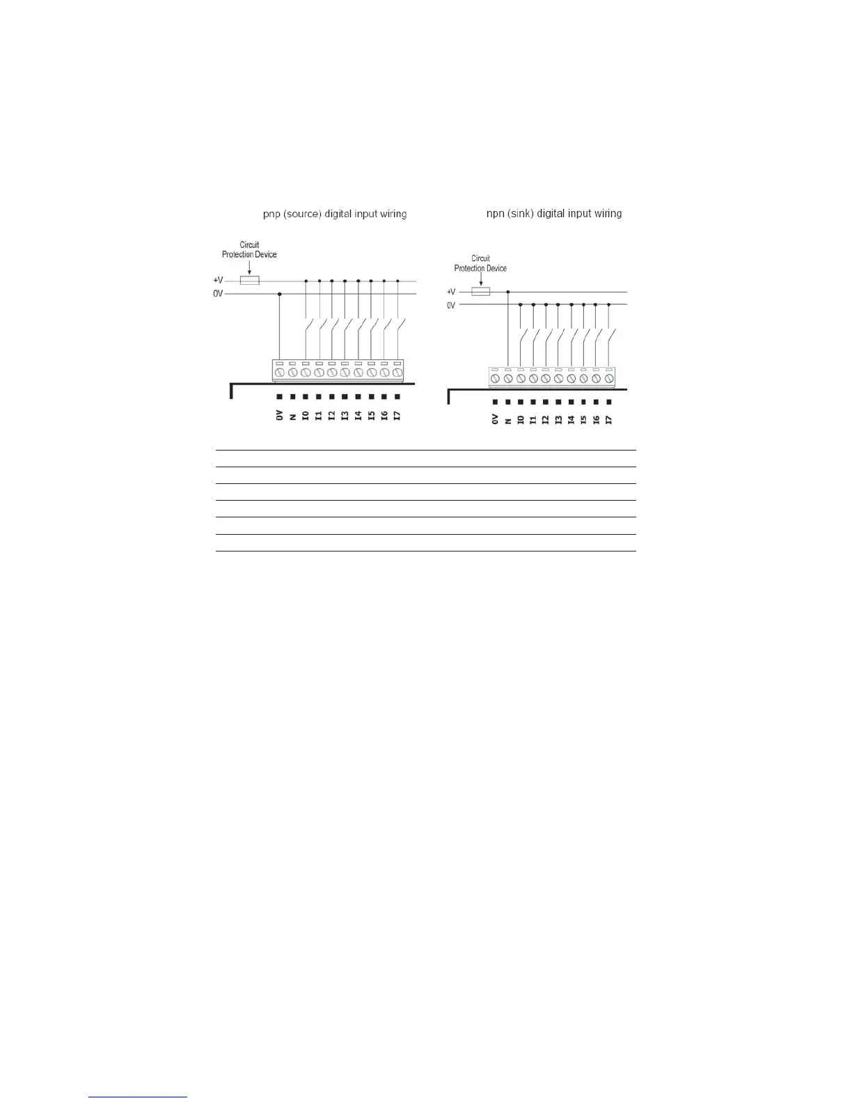
Figure 4-2. Digital Inputs Used as pnp (Source)
4-5