Model 6 Motor Control Centers 80459-641-01E
Section 4—Installing the MCC 10/2012
© 1999–2012 Schneider Electric All Rights Reserved34
ENGLISH
Joining NEMA Type 3R Sections This section provides instructions for joining NEMA Type 3R MCC sections
(manufactured after February 1998).
NOTE: All NEMA Type 3R sections manufactured after February 1998 are
approximately 93 in. (2362 mm) from the bottom of the section to the top of
the deflector.
1. Turn off all power supplying this equipment before working on or inside
the equipment, and follow lockout/tagout procedures. Always use a
properly rated voltage sensing device to confirm the power is off.
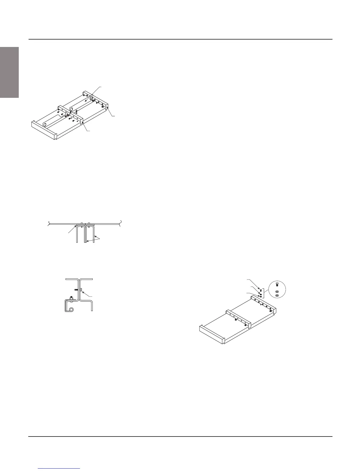
2. Remove the right section (see Figure 25) back plate.
NOTE: Steps 3 and 4 apply only if a new section is being added to an
existing MCC line-up. If installing a new line-up, skip to Step 5.
3. Remove the end deflector cap from the right side of the existing NEMA
Type 3R section (see Figure 24). Also, remove the mid deflector cap
from the section being added to the right.
4. Remove the end closing plate from the right side of the existing section.
5. After placing the structures side-by-side, join them as described in
“Joining NEMA Type 1 / NEMA Type 1 Gasketed / NEMA Type 12
Sections” on page 20.
6. Re-attach the back plate (removed in Step 2) to the right section using
the additional hardware supplied. Attach the right side to the multi-
section bracket (see Figure 25).
7. Install the mid deflector, ensuring both top plate flanges are covered
(see Figure 24).
8. Using the six 10-32 screws supplied, secure the left front vertical
channel of the NEMA Type 3R extension to the right front vertical
channel of the NEMA Type 3R extension (see Figure 26).
9. If the lifting angle is to be removed from the sections after installation,
replace all hardware in the order shown (see Figure 27).
Figure 24: Remove Mid and End Deflector
Caps from the Top of the MCC
Top View
Lifting angle
End deflector
Mid deflector
Figure 25: Attach the Multi-section Bracket
Front
Rear
Left section
back plate
Right section
back plate
Multi-section
back bracket
Section corner
channels
Figure 26: Secure the Vertical Channels
Right section
10–32 screw
Left section
Figure 27: Replace Lifting Angle Hardware
3/8 in. bolt
Steel washer
Seal ring