80459-641-01E Model 6 Motor Control Centers
10/2012 Appendix A—Removal and Installation of Horizontal Bus Barrier Panels
© 1999–2012 Schneider Electric All Rights Reserved
113
ENGLISH
Appendix A—Removal and
Installation of Horizontal Bus
Barrier Panels
This appendix contains installation and removal instructions for the
horizontal bus barrier panels in 15 in. (381 mm) and 20 in. (508 mm) deep
Model 6 Motor Control Centers manufactured by Schneider Electric.
Removal 1. Turn off all power supplying this equipment before working on or inside
the equipment, and follow lockout/tagout procedures. Always use a
properly rated voltage sensing device to confirm the power is off.
2. With one hand, slide the left panel to the right until it unsnaps from the
right panel.
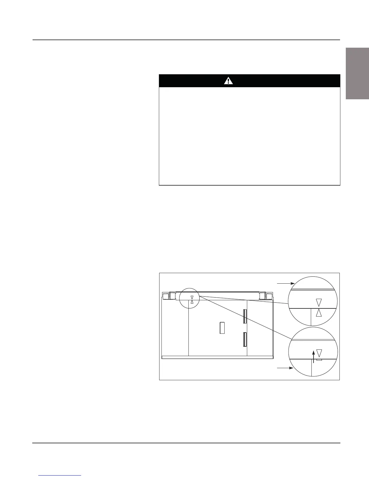
3. Align the arrows on the left panel and top track as shown in Figure 129.
Lift the panel out of the bottom track, and remove the panel.
4. Align the arrows on the right panel and top track as shown in Figure 129.
Lift the panel out of the bottom track, and remove the panel.
DANGER
HAZARD OF ELECTRIC SHOCK, EXPLOSION, OR ARC FLASH
• Apply appropriate personal protective equipment (PPE) and follow safe
electrical work practices. See NFPA 70E or CSA Z462.
• This equipment must only be installed and serviced by qualified
electrical personnel.
• Turn off all power supplying this equipment before working on or inside
equipment.
• Always use a properly rated voltage sensing device to confirm power is
off.
• Replace all devices, doors, and covers before turning on power to this
equipment.
Failure to follow this instruction will result in death or serious injury.
Figure 129: Aligning the Arrows on the Panels
Align arrows
Lift up on panel