14
Installation
DANGER
Risque d’explosion. Couper le courant ou s’assurer que l’emplacement est designe
non dangereux avant de replacer le aucon composant.
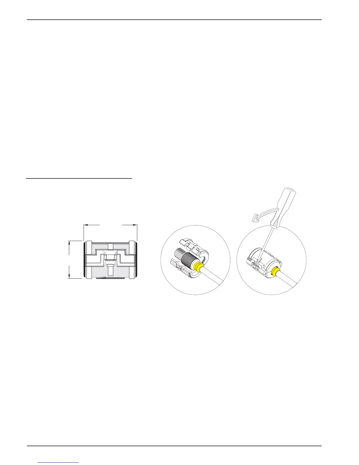
3.1.2.1 Attaching a sc Sensor with a Quick-connect Fitting in a Hazardous Location
The sensor cable is supplied with a keyed quick-connect fitting for easy attachment to the
controller, see Figure 5. For hazardous locations, a connector safety lock
(Cat. No. 6139900) must be installed. Retain the connector cap to seal the connector
opening in case the sensor must be removed.
1. Remove the connector cap from sc100 controller. Retain the connector cap to seal the
connector opening in case the sensor must be removed.
2. Connect the sensor connector to the plug on the sc100.
3. Install a connector safety lock (Figure 7). Align the lock over the connector and
squeeze the two halves together to lock. To remove the connector safety lock by
inserting a small flat-bladed screwdriver into the locking groove. Pivot the screwdriver
away from the groove and separate the two halves (Figure 7).
Figure 7 Installing the Connector Safety Lock
3.2 Connecting the Sensor to the sc1000
3.2.1 Connecting the Sensor using the Quick-connect Fittings
1. Unscrew the connector cap from the controller. Retain the connector cap to seal the
connector opening in case the sensor must be removed.
2. Push the connector into the socket.
3. Hand-tighten the union nut.
Note: Do not use the middle connection for the sensors as this is reserved for the display module.
3.3 Using the Digital Gateway
The digital gateway is designed to provide a digital interface to the controller. The
non-sensor end is wired to the sc100 or sc1000 controller in a non-hazardous location as
38.1 mm
(1.50 inches)
38.1 mm
(1.50 inches)