Model 6 Motor Control Centers 80459-641-01E
Section 4—Installing the MCC 10/2012
© 1999–2012 Schneider Electric All Rights Reserved32
ENGLISH
the short flange is flush with the back of the corner channel and that the
holes in the bracket line up with the holes in the corner channel.
9. Attach a right splice bracket (see Figure 21), 94 in. (2388 mm) long, to
the left splice bracket installed in Step 7 using six 10–32 flat Phillips
head screws contained in the kit. Ensure that the short flange is behind
the flange of the left splice bracket. The right splice bracket will extend
below the left splice bracket by approximately 1 in. (25 mm) when
properly installed.
10. Install a right splice bracket (see Figure 21), 94 in. (2388 mm) long, to
the left splice bracket installed in Step 8 using six 10–32 flat Phillips
head screws contained in the kit. Ensure that the short flange is in front
of the flange of the left splice bracket. The right splice bracket will extend
below the left splice bracket by approximately 1 in. (25 mm) when
properly installed.
11. Position the structures that are to be spliced. Check that the fronts are
flush to ensure proper alignment of all components.
12. Splice sections using the instructions in the Model 5 Instruction Bulletin
(8998IM9101R5/92) if joining to a Model 5 MCC, or the instructions on
28 of this instruction bulletin if joining to a Model 6 MCC.
NOTE: When splicing the horizontal bus between the new and existing
MCC sections, remove the splice bars contained in the leftmost section
of the existing MCC. Discard the splice bars. Install the horizontal bus
splice assembly provided in this kit using the instructions beginning on
35 of this bulletin. Use the remaining six 1/4–20 hex head screws
provided in the kit to splice the corner channels of the existing MCC to
the right splice brackets installed in Steps 9 and 10.
13. Using the 10–32 hex head screws removed in Step 3, re-attach the back
plate (see Figure 22) to the rightmost section of the new MCC. Install the
back bracket (see Figure 21 on page 31) under the back plate using the
left side holes of the back bracket. Ensure that the notch at the top of the
back bracket is installed toward the new MCC section.
14. Using the 10–32 screws removed in Step 3, re-attach the back plate
(see Figure 22) to the right section.
15. Install the splice deflector (see Figure 21 on page 31) to the rightmost
section of the MCC being added. Use the five 1/4–20 screws supplied in
the kit. Ensure that both top plate flanges are covered.
16. Install five of the 1/4–20 screws removed in Step 2 through the splice
deflector and into the top plate of the leftmost section of the existing
MCC.
17. Using the six 10–32 screws supplied in the kit, secure the right front
vertical channel of the new NEMA Type 3R enclosure to the left front
vertical channel of the existing NEMA Type 3R enclosure.
NOTE: Install the screws through the clearance holes in the left front
vertical channel of the existing MCC into the right front vertical channel
of the new MCC.
18. Before energizing the equipment, replace all covers and barriers.
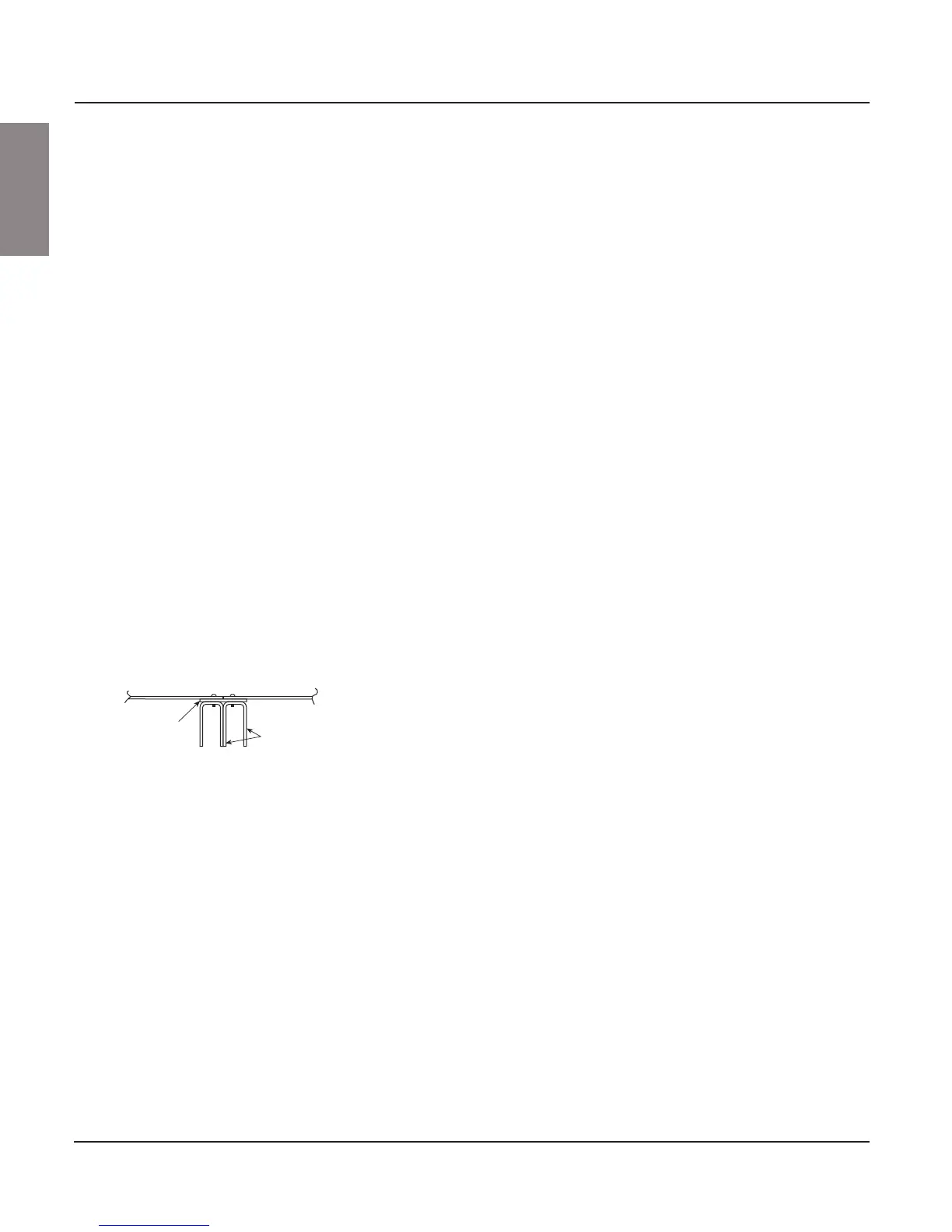
Figure 22: Re-attaching the Back Plates
Front
Rear
Left section
back plate
Right section
back plate
Multi-section
back bracket
Section corner
channels