80459-641-01E Model 6 Motor Control Centers
10/2012 Appendix A—Removal and Installation of Horizontal Bus Barrier Panels
© 1999–2012 Schneider Electric All Rights Reserved
115
ENGLISH
Fixed Barrier
Removal 1. Turn off all power supplying this equipment before working on or inside
the equipment, and follow lockout/tagout procedures. Always use a
properly rated voltage sensing device to confirm the power is off.
2. A captive rivet at the bottom of each bus barrier panel secures the
panels to mounting brackets on the MCC (see Figure 132 below, and
Figures Figure 133 and Figure 134 on 116).
3. Firmly grasp the head of the left side rivet and pull until the rivet releases
from the mounting bracket.
4. Pull out on the bottom of the left side panel until the tab at the top of the
panel is clear of the top track (see Figure 133 on page 116).
5. Remove the panel from the MCC.
6. Repeat steps 3–5 for the right side panel.
DANGER
HAZARD OF ELECTRIC SHOCK, EXPLOSION, OR ARC FLASH
• Apply appropriate personal protective equipment (PPE) and follow safe
electrical work practices. See NFPA 70E or CSA Z462.
• This equipment must only be installed and serviced by qualified
electrical personnel.
• Turn off all power supplying this equipment before working on or inside
equipment.
• Always use a properly rated voltage sensing device to confirm power is
off.
• Replace all devices, doors, and covers before turning on power to this
equipment.
Failure to follow this instruction will result in death or serious injury.
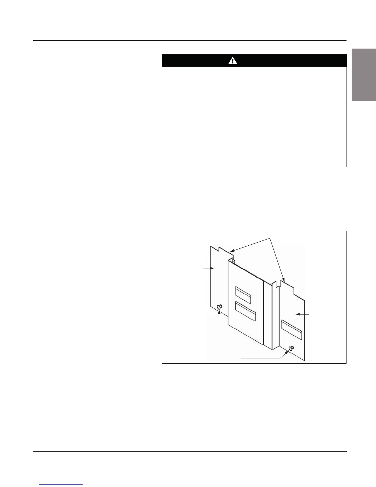
Figure 132: Fixed Horizontal Bus Barrier
Plastic captive rivets
Right side
panel
Left side
panel
Tabs