80459-641-01E Model 6 Motor Control Centers
10/2012 Section 4—Installing the MCC
© 1999–2012 Schneider Electric All Rights Reserved
31
ENGLISH
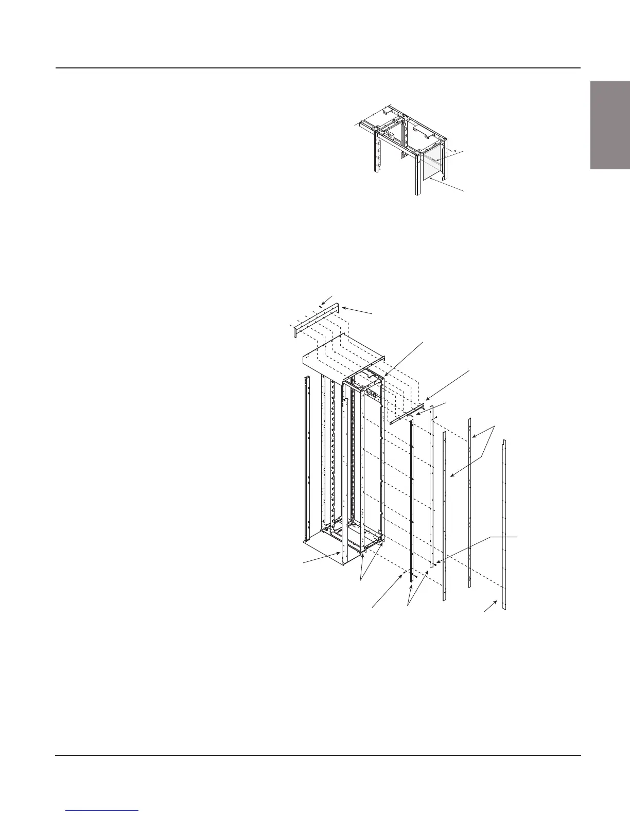
6. Install the deflector bracket (see Figure 21) on the rightmost section of
the MCC being added using two 8-32 Phillips head screws included in
the kit. The same holes from which the rivets were removed will be used
to mount the deflector bracket. Ensure that the top holes of the bracket
align with the holes in the top plate of the enclosure.
7. Attach a left splice bracket (see Figure 21), 90 in. (2286 mm) long, to the
front corner channel of the rightmost section of the MCC being added
using six 1/4–20 screws contained in the kit. Ensure that the short flange
is flush with the front of the corner channel and that the holes in the
bracket line up with the holes in the corner channel.
8. Install a left splice bracket (see Figure 21 on page 31), 90 in. (2286 mm)
long, to the rear corner channel of the rightmost section of the MCC
being added using six 1/4–20 screws contained in the kit. Ensure that
Figure 20: Removing the Insulating Barrier
Figure 21: Installing the Deflector Bracket
Rivets
Insulating barrier
1/4–20 screws
Splice deflector
Section
being added
Deflector
bracket
8–32
screws
Right splice bracket
[94 in. (2388 mm) long]
1/4–20 screws
Back
bracket
Left splice bracket
[90 in. (2286 mm)
long]
10–32
flat Phillips
head screws
Corner
channel
Front
vertical
channel