80459-641-01E Model 6 Motor Control Centers
10/2012 Section 4—Installing the MCC
© 1999–2012 Schneider Electric All Rights Reserved
25
ENGLISH
Securing Structures to Floor—Seismic
Hazard
1
Designated Locations
Each section must be anchored per detail supplied by engineer of record to
the load-bearing path of the building structural system. For floor mounting
locations, see Figure 14 (NEMA Type 1, Type 1 Gasketed, and Type 12
enclosures) or Figure 16 on page 26 (NEMA Type 3R enclosures). Use
0.50 in. or 0.75 in. grade 5 or higher bolts and Belleville washers. Torque
bolts to the value specified by the manufacturer of the anchor.
1
Seismic hazard for site specific locations as defined by the current edition of the International Building Code or NFPA 5000 or relevant local building code or
consulting engineer of record.
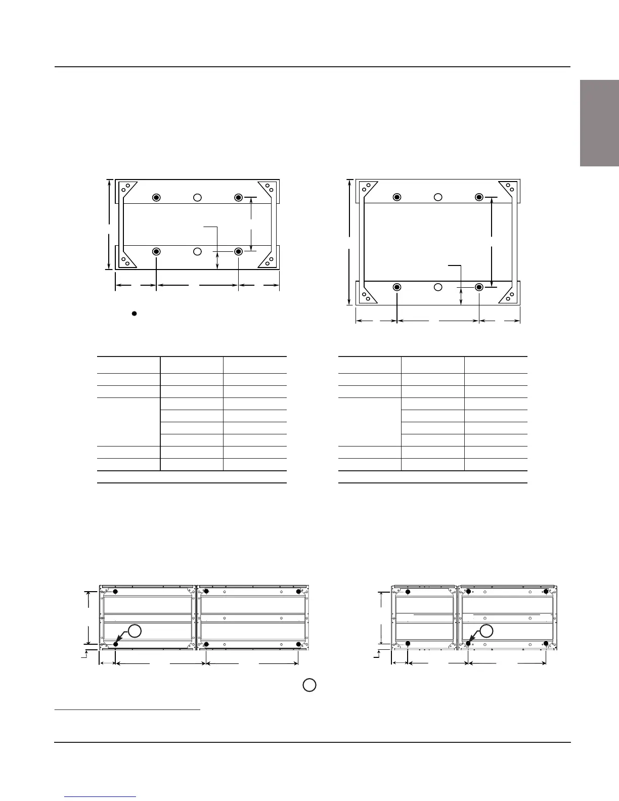
Figure 14: NEMA Type 1, Type 1 Gasketed, and Type 12 Seismic Tie-Down Locations
= Seismic Tie-Down Locations
B
C
A
B
D
C
A
A
D
A
E
E
15 in. (381 mm) Section Dimensions
Letter Section Width Dimension
A N/A 5.00 in. (127 mm)
B N/A 15.00 in. (381 mm)
C
20.00 in. (508 mm) 10.00 in. (254 mm)
25.00 in. (635 mm) 15.00 in. (381 mm)
30.00 in. (762 mm) 20.00 in. (508 mm)
35.00 in. (889 mm) 25.00 in. (635 mm)
D N/A 9.98 in. (253 mm)
E N/A 2.50 in. (64 mm)
N/A = Not applicable
20 in. (508 mm) Section Dimensions
Letter Section Width Dimension
A N/A 5.00 in. (127 mm)
B N/A 20.00 in. (508 mm)
C
20.00 in. (508 mm) 10.00 in. (254 mm)
25.00 in. (635 mm) 15.00 in. (381 mm)
30.00 in. (762 mm) 20.00 in. (508 mm)
35.00 in. (889 mm) 25.00 in. (635 mm)
D N/A 14.98 in. (380 mm)
E N/A 2.50 in. (64 mm)
N/A = Not applicable
NOTE: The dimensions shown are tie-down locations within
individual MCC sections. Refer to factory supplied drawings to
determine appropriate anchor locations for the equipment pad.
Figure 15: Seismic Tie-Down Locations for 18-Pulse AC Drive MCC Sections
Structure Anchoring
Locations
(Typical of 9)
2.50
(64)
2.50
(64)
5.00
(127)
5.00
(127)
15.72
(400)
29.70
(754)
25.58
(650)
19.70
(500)
20.52
(521)
15.72
(400)
50 in. (1270 mm) Wide X 20 in. (508 mm) Deep65 in. (1651 mm) Wide X 20 in. (508 mm) Deep
Structure anchoring
locations (typical of 9)
A A
A
Dual dimensions: Inches
(mm)