80459-641-01E Model 6 Motor Control Centers
10/2012 Section 4—Installing the MCC
© 1999–2012 Schneider Electric All Rights Reserved
23
ENGLISH
4. Locate two clearance holes for 1/4-20 hardware on the inside surface of
the top section side channels. The front clearance hole is in the left
section and is accessible after removal of the top wireway cover (see
Figure 11F on page 22).
5. The rear clearance hole is in the right section. In most cases, it will be
necessary to remove the section back plate or the top plate to gain
access to the rear clearance hole and install the screw (see Figure 11G).
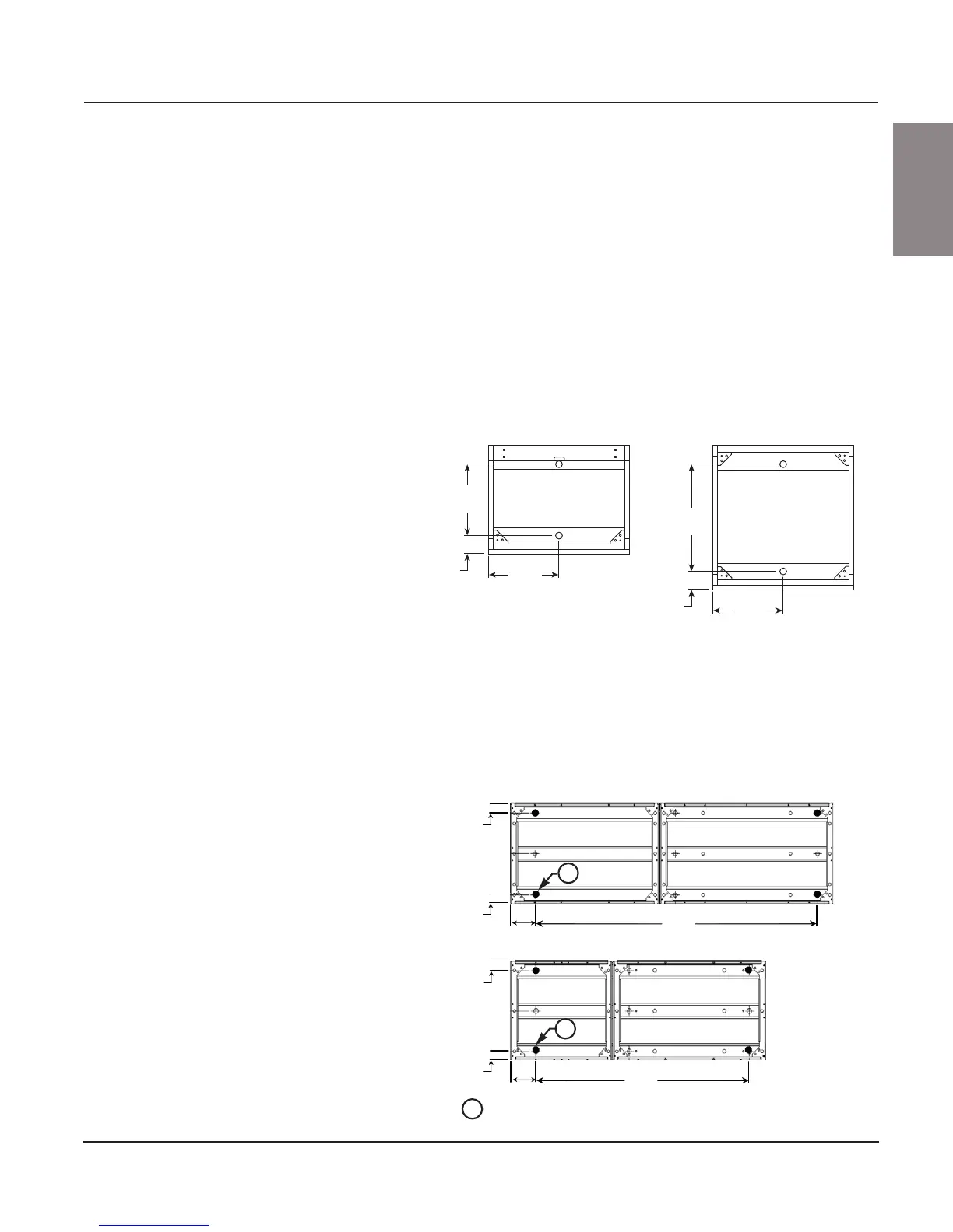
Securing Structures to the Floor
(Non-Seismic Applications, see page 25 for
Seismic Applications)
Fasten each section to the floor (see Figure 12) using 1/2 in. or 3/4 in.,
grade 5 or higher, bolts, and flat washers (furnished by customer).
0.88 in. (22 mm) diameter base channel mounting holes provide clearance
for bolt expansion anchors for 1/2 in. bolts.
NOTE: Although sections are free-standing, floor fastening prevents
movement, thereby preventing conduit connection damage.
Figure 12: Standard Base Channel Mounting
Figure 13: Base Channel Mounting For 18-Pulse AC Drive MCC
Sections
20 Wide x 15 Deep
(508) (381)
10.00
(254)
2.50
(64)
10.00
(254)
15.00
(381)
2.50
(64)
10.00
(254)
20 Wide x 20 Deep
(508) (508)
Dual dimensions: Inches
(mm)
2.50
(64)
2.50
(64)
2.50
(64)
2.50
(64)
5.00
(127)
5.00
(127)
55.28
(1404)
40.22
(1021)
Structure anchoring
locations (typical of 4)
A
A
A
50 in. (1270 mm) Wide X 20 in. (508 mm) Deep
65 in. (1651 mm) Wide X 20 in. (508 mm) Deep
Dual dimensions: Inches
(mm)