Model 6 Motor Control Centers 80459-641-01E
Section 10—Expansion 10/2012
© 1999–2012 Schneider Electric All Rights Reserved98
ENGLISH
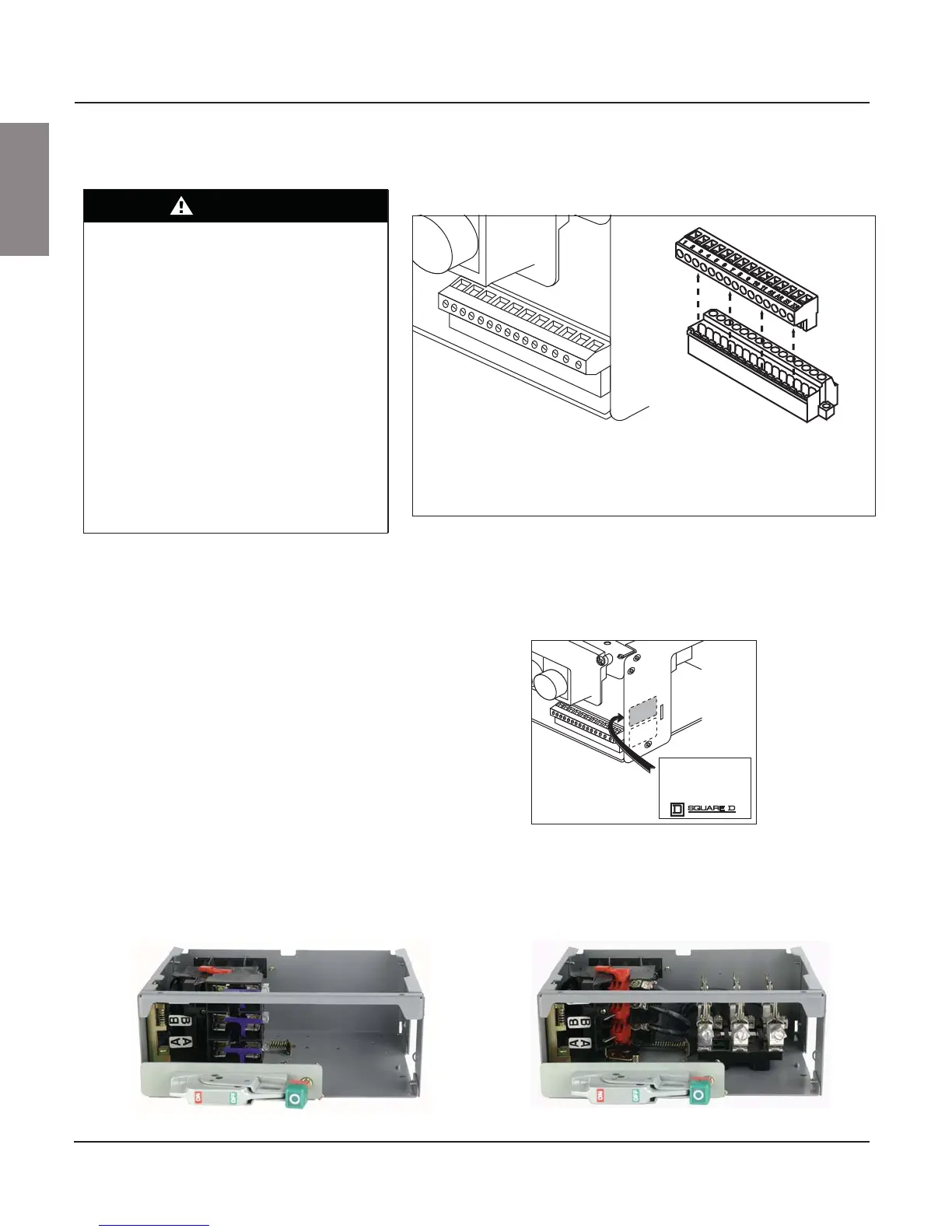
Control and Load Wiring Pull-apart control terminals (see Figure 124) are mounted on the floor of the
unit adjacent to the wiring port on the right side. Terminate field control
wiring on the removable portion of the block.
Cable Connection Torque Values Refer to the torque label on the right inside wall of the unit for load terminal
wire and torque requirements (see Figure 125).
Fuse clips in six-inch (52 mm) units accommodate 600 V, Class J fuses only.
The switch mounted fuse base (see Figure 126) is configured either for 30 A
or 60 A fuses. The bottom plate mounted fuse base accepts 100 A fuses.
DANGER
HAZARD OF ELECTRIC SHOCK,
EXPLOSION, OR ARC FLASH
• Apply appropriate personal protective
equipment (PPE) and follow safe electrical
work practices. See NFPA 70E or
CSA Z462.
• This equipment must only be installed and
serviced by qualified electrical personnel.
• Turn off all power supplying this equipment
before working on or inside equipment.
• Always use a properly rated voltage sensing
device to confirm power is off.
• Replace all devices, doors, and covers
before turning on power to this equipment.
Failure to follow this instruction will result
in death or serious injury.
Figure 124: Pull-apart Terminals
1 2 3 4 5 6 7 8 9 10 11 A1 A2 X1 X2
10 A Control Wire Terminal Block
• To separate or remove the top portion of the terminal block from its base, grasp the top
half and pull apart as shown.
• Each terminal is rated for one 16-12 AWG wire or two 16 AWG wires.
• Torque terminal screws to 5 lb-in (0.5 N•m).
Figure 125: Typical Unit Torque Label
1 2 3 4 5 6 7 8 9 10 11 A1 A2 X1 X2
UNIT MOTOR CONNECTIONS MUST
BE SIZED PER 60 C OR 75 C
NEC WIRE RATING.
USE COPPER WIRE ONLY.
MAINTAIN TORQUE VALUE OF
20 lb-in FOR THESE CONNECTIONS.
80438-064-01
Figure 126: Fuse Bases
Switch Mounted Fuse Base Bottom Plate Mounted Fuse Base