Model 6 Motor Control Centers 80459-641-01E
Section 7—Motor Logic™ Solid-State Overload Relay (SSOLR) 10/2012
© 1999–2012 Schneider Electric All Rights Reserved72
ENGLISH
Adjustment
Turn off all power supplying this equipment before working on or inside the
equipment, and follow lockout/tagout procedures. Always use a properly
rated voltage sensing device to confirm the power is off.
Overload adjustment information is located on a label inside the unit door
(Figure 103) of starter units equipped with the Motor Logic overload relay.
DANGER
HAZARD OF ELECTRIC SHOCK, EXPLOSION, OR ARC FLASH
• Apply appropriate personal protective equipment (PPE) and follow safe
electrical work practices. See NFPA 70E or CSA Z462.
• This equipment must only be installed and serviced by qualified
electrical personnel.
• Turn off all power supplying this equipment before working on or inside
equipment.
• Always use a properly rated voltage sensing device to confirm power is
off.
• Replace all devices, doors, and covers before turning on power to this
equipment.
Failure to follow this instruction will result in death or serious injury.
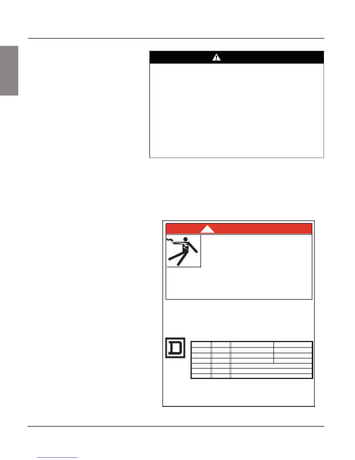
Figure 103: Unit Adjustment Label
DANGER
Trip current rating is 1.25 times the overload relay's current adjustment dial setting.
Instructions above assume the motor is applied at its rated ambient temperature. For other
conditions, consult the motor manufacturers for current capacity. NOTE: For part winding and
multi-speed applications, use the MFLC of each motor winding as a basis for overload
adjustment.
Trip and alarm contact ratings: NEMA A600 and NEMA P300.
SOLID - STATE OVERLOAD RELAY
CURRENT RANGE:
SIZE 00C 3 - 9A 1.5 - 4.5A (2 PASSES) 1 - 3A (3 PASSES)
SIZE 0
SIZE 1
SIZE 2
SIZE 3
SIZE 4
6 - 18A
9 - 27A
15 - 45A
30 - 90A
45 - 135A
3 - 9A (2 PASSES)
4.5 -13.5A (2 PASSES)
MULTIPLE PASSES NOT AVAILABLE
MULTIPLE PASSES NOT AVAILABLE
MULTIPLE PASSES NOT AVAILABLE
2 - 6A (3 PASSES)
3 - 9A (3 PASSES)
* Passes refer to multiple looping through overload windows.
Failure to follow these instructions will result in death,
serious injury or equipment damage.
Turn off power supplying equipment
before working inside.
For fusible switch starter units, power fuses
must be selected in accordance with Article
430 of the NEC. Class RK5 fuses are
recommended for NEMA rated applications.
HAZARD OF ELECTRIC SHOCK, BURN OR
EXPLOSION
80438-651-01 G
•
REV
OPERATING INSTRUCTIONS;
For continuous-rated motors with
service factors of 1.0, multiply the motor
full-load current (MFLC) by the number of passes through the overload relay's
windows (1,2 or 3) and set the overload relay's current adjustment dial to 90% of this
value. For continuous-rated motors with service factors of 1.15 to 1.25, multiply the
MFLC by the number of passes through the overload relay's windows (1,2 or 3) and
set the overload current adjustment dial to this value.
Use only Class J fuses for Compac™ 6 units.
•
•
SIZE 00B
1.5 - 4.5A
0.75 - 2.25A (2 PASSES)
0.5 - 1.5A (3 PASSES)