Analog output connections
WARNING
Potential Electrocution Hazard. Always disconnect power to the
instrument when making electrical connections.
WARNING
Potential electrocution hazard. In order to maintain the NEMA/IP
environmental ratings of the enclosure, use only conduit fittings and
cable glands rated for at least NEMA 4X/IP66 to route cables in to the
instrument.
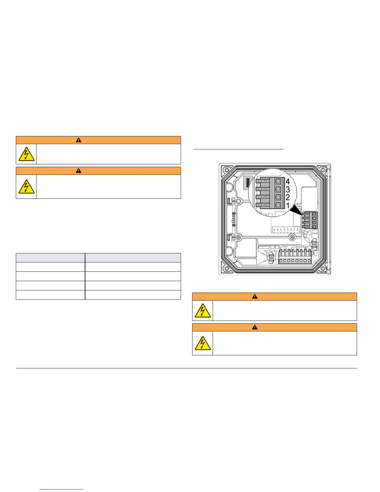
Two isolated analog outputs (1 and 2) are provided (Figure 8). Such
outputs are commonly used for analog signaling or to control other
external devices.
Make wiring connections to the controller as shown in Figure 8 and
Table 3.
1ote Figure 8 sKoZs tKe EacN of tKe controller cover and not tKe inside of tKe
Pain controller coPpartPent.
Table 3 Output connections
Recorder wires Circuit board position
Output 2– 4
Output 2+ 3
Output 1– 2
Output 1+ 1
1. Open the controller cover.
2. Feed the wires through the strain relief.
3. Adjust the wire as necessary and tighten the strain relief.
4. Make connections with twisted-pair shielded wire and connect the
shield at the controlled component end or at the control loop end.
• Do not connect the shield at both ends of the cable.
• Use of non-shielded cable may result in radio frequency emission
or susceptibility levels higher than allowed.
• Maximum loop resistance is 500 ohm.
5. Close the controller cover and tighten the cover screws.
6. Configure outputs in the controller.
Figure 8 Analog output connections
Discrete input wiring connections
WARNING
Potential Electrocution Hazard. Always disconnect power to the
instrument when making electrical connections.
WARNING
Potential electrocution hazard. In order to maintain the NEMA/IP
environmental ratings of the enclosure, use only conduit fittings and
cable glands rated for at least NEMA 4X/IP66 to route cables in to the
instrument.
18 (nglisK