Model 6 Motor Control Centers 80459-641-01E
Section 8—Mag-Gard™ and PowerPact™ Motor Circuit Protector Settings 10/2012
© 1999–2012 Schneider Electric All Rights Reserved74
ENGLISH
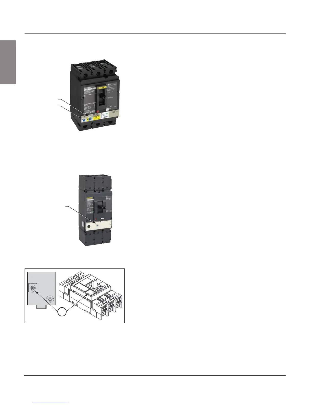
To access the PowerPact H- and J-frame Full Load Amps (FLA) and
Instantaneous Trip setting (Im) dials:
1. Turn off all power supplying this equipment before working on or inside
the equipment, and follow lockout/tagout procedures. Always use a
properly rated voltage sensing device to confirm the power is off.
2. Place the unit handle in the OFF position and open the door.
3. To set the FLA and Im dials, refer to the PowerPact Motor Circuit
Protector Settings instruction bulletin (48940-260-01) shipped with the
equipment.
NOTES: • Select replacement Mag-Gard or PowerPact Motor Circuit
Protectors for MCCs using the voltage and current ratings
listed in the Model 6 MCC Catalog (8998CT9701) in addition to
the Mag-Gard or PowerPact selection tables in the Square D
Digest.
• These circuit breakers are suitable for motors with locked-rotor
indicating code letters based on applicable national codes and
standards. For other motors, consult your local Schneider
Electric field sales representative.
To access the PowerPact L-frame trip adjustment dial (Isd):
1. Turn off all power supplying this equipment before working on or inside
the equipment, and follow lockout/tagout procedures. Always use a
properly rated voltage sensing device to confirm the power is off.
2. Place the unit handle in the OFF position and open the door.
3. Set the overcurrent trip setting by adjusting the switch labeled "Isd" as
shown in Figure 106. The dial is labeled in amperes. Refer to instruction
bulletin 48940-310-01, Micrologic™ 0, 1, 2, and 3 Trip Units—User
Guide for more information on trip settings. This instruction bulletin is
shipped with the equipment.
After obtaining the motor full load current from the motor nameplate, select
an adjustable trip set-point to test start the motor. Further adjustments may
be required because of motor load characteristics. Refer to applicable
national installation codes for permissible set-points.
To access the PowerPact P-frame Instantaneous Trip setting (Im) dial:
1. Turn off all power supplying this equipment before working on or inside
the equipment, and follow lockout/tagout procedures. Always use a
properly rated voltage sensing device to confirm the power is off.
2. Place the unit handle in the OFF position and open the door.
3. Make adjustments as follows:
a. For ET1.0I and ET1.0M electronic trip units, adjust instantaneous trip
(Ii) by adjusting switch A (see Figure 107). Switch settings are
multiples of the frame rating.
b. For Micrologic electronic trip units, see the instruction bulletin
shipped with the circuit breaker.
After obtaining the motor full load current from the motor nameplate, select
an adjustable trip set-point to test start the motor. Further adjustments may
be required because of motor load characteristics. Refer to applicable
national installation codes for permissible set-points.
Figure 105: PowerPact H- and J-frame
Magnetic Trip Adjustment
Instantaneous
trip setting dial
Full load
amps dial
Figure 106: PowerPact L-frame
Instantaneous Trip Adjustment
Trip adjustment
dial
Figure 107: PowerPact P-frame
Instantaneous Trip Adjustment
A