Model 6 Motor Control Centers 80459-641-01E
Section 6—Maintaining the MCC 10/2012
© 1999–2012 Schneider Electric All Rights Reserved58
ENGLISH
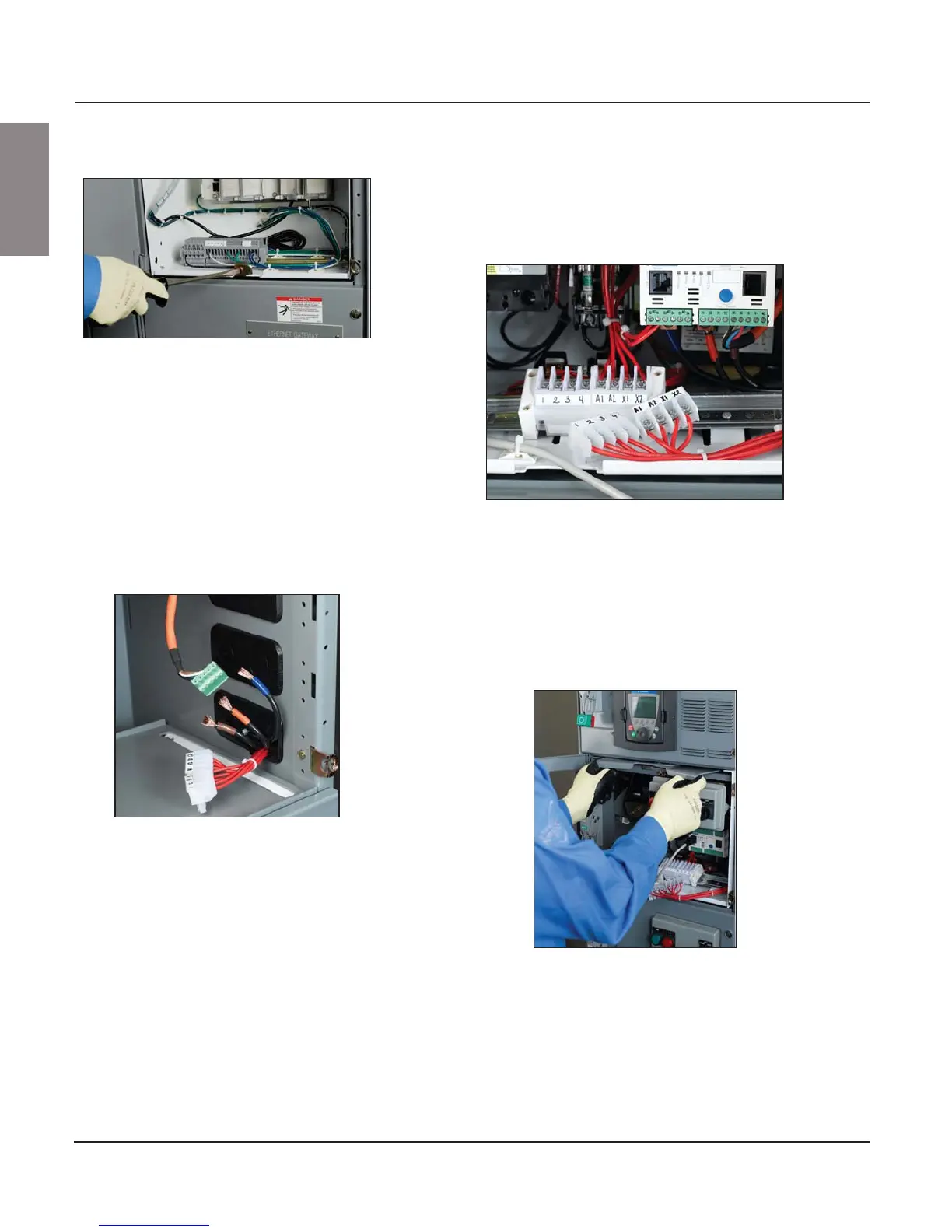
5. Disconnect the power wiring from the starter terminals or, if provided,
the power terminal blocks. Tag the terminations for re-installation (see
Figure 76).
Remove the top portion of the pull-apart control terminal blocks to which
field wiring is connected.
6. Push the power leads and the top portion of the control pull-apart
terminal blocks through the wiring port and into the vertical wire trough
(see Figure 77).
7. Pull forward on the twin handle cam mechanism located at the top front
of the unit to rack the unit partially out of the structure (see Figure 78).
This action disconnects the power stabs from the vertical bus. Continue
pulling forward until the handles are fully extended.
Figure 75: Releasing the Lock-in Device
(when supplied)
Figure 76: Disconnected Terminal Blocks
Figure 77: Power Leads and Top of
Terminal Blocks Fed Through
Wiring Port
Figure 78: Pulling the Twin Handle Cam Mechanism Forward