EasyManuals Logo

Hach sc200 User Manual

Hach sc200
875 pages
To Next Page IconTo Next Page
To Previous Page IconTo Previous Page
Page #788 background imageLoading...
Page #788 background image
Model 6 Motor Control Centers 80459-641-01E
Appendix A—Removal and Installation of Horizontal Bus Barrier Panels 10/2012
© 1999–2012 Schneider Electric All Rights Reserved116
ENGLISH
Installation 1. Turn off all power supplying this equipment before working on or inside
the equipment, and follow lockout/tagout procedures. Always use a
properly rated voltage sensing device to confirm the power is off.
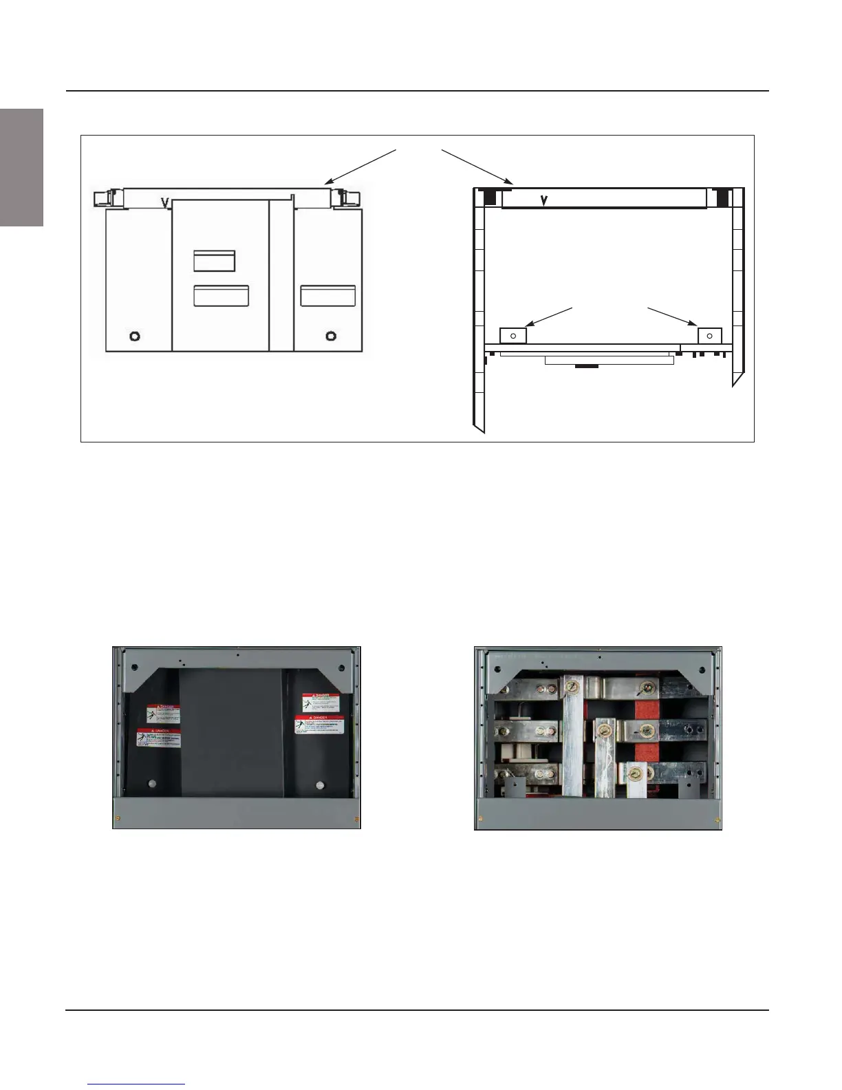
2. Insert the tab on the right side panel into the top track on the right side of
the MCC and set it into place (see Figure 132 on page 115 and
Figure 133).
3. Secure the right side panel by pushing the rivet firmly into the hole of the
mounting bracket.
4. Repeat steps 2 and 3 for the left side panel.
Figure 133: Horizontal Bus Barrier Installation and Removal
Mounting brackets
Top track
Barrier Installed Barrier Removed
Figure 134: Barrier Installed and Removed
Installed Removed

Table of Contents

Other manuals for Hach sc200

Questions and Answers:

Question and Answer IconNeed help?

Do you have a question about the Hach sc200 and is the answer not in the manual?

Hach sc200 Specifications

General IconGeneral
Enclosure RatingNEMA 4X/IP66
Operating Temperature-20 to 60 °C (-4 to 140 °F)
Ambient Temperature-20 to 60 °C (-4 to 140 °F)
Enclosure MaterialPolycarbonate
Operating Humidity0 to 95% non-condensing
Relay OutputsUp to 4 SPDT relays
Storage Conditions-40 to 70 °C (-40 to 158 °F)
DisplayGraphical LCD
Inputs2 digital sensor inputs
Outputs4-20 mA
Power Supply100 to 240 VAC, 50/60 Hz
Analog Outputs2 or 4, 0/4-20 mA
CertificationsCE
CommunicationModbus RTU, HART
Dimensions144 x 144 mm
MountingPanel mount
Output4-20 mA
Power Requirements (Voltage)100 to 240 VAC
Warranty1 year
Weight1.2 kg

Related product manuals