80459-641-01E Model 6 Motor Control Centers
10/2012 Section 13—Circuit Breaker and Fusible Switch Replacement
© 1999–2012 Schneider Electric All Rights Reserved
111
ENGLISH
Section 13—Circuit Breaker
and Fusible Switch
Replacement
For F-frame and K-frame circuit breakers and 100/200 A fusible switches,
Schneider Electric recommends replacing the entire disconnect assembly
instead of replacing the circuit breaker or fusible switch. The disconnect
assembly includes the operator mechanism and the appropriate circuit
breaker or switch. Replacing the entire disconnect assembly requires the
removal of three screws (two from the left side of the assembly and one
inside the back of the assembly). This procedure is much simpler and
quicker than replacing an individual circuit breaker or switch. See Schneider
Electric bulletin Disconnect Assembly Replacement (80439-666-01) for
disconnect assembly installation instructions.
For PowerPact™ H-frame and J-Frame circuit breakers, order a
replacement circuit breaker only. To replace the circuit breaker:
1. Turn off all power supplying this equipment before working on or inside
the equipment, and follow lockout/tagout procedures. Always use a
properly rated voltage sensing device to confirm power is off.
2. Remove the control unit from the MCC. See “Removing the Control Unit”
on page 57.
3. Open the line insulator tabs.
4. Loosen the screw lugs for the line/load cables; detach the cables.
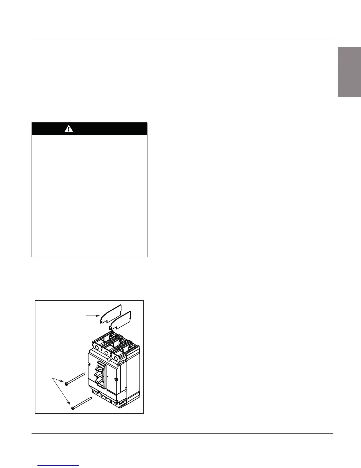
5. Remove the two circuit breaker mounting screws (see Figure 128).
6. Remove the circuit breaker from the unit and then remove the phase
insulators from the breaker (see Figure 128).
7. Unpack the new circuit breaker and reinstall the circuit breaker phase
insulators in the slots provided on the circuit breaker.
8. Place the circuit breaker in the mounting pan, making sure that the line
insulator is in position under the circuit breaker. Secure the circuit
breaker with the two mounting screws provided.
9. Attach the line/load cables to the breaker using the screw lugs removed
in step 4; torque the screw lugs to the value indicated on the circuit
breaker.
10. Close the line insulator tabs.
11. Reinstall the control unit in the MCC. Close and fasten the door.
Always use replacement devices of the same type and rating as the device
being removed. Using a different type of disconnect or one with a different
rating may alter the short circuit ratings of the motor control center.
Contact the MCC Technical Assistance Group (TAG) before installing a
circuit breaker with a different rating. See “Appendix D—Technical Support”
on page 131 for the MCC TAG technical support number.
DANGER
HAZARD OF ELECTRIC SHOCK,
EXPLOSION, OR ARC FLASH
• Apply appropriate personal protective
equipment (PPE) and follow safe electrical
work practices. See NFPA 70E or
CSA Z462.
• This equipment must only be installed and
serviced by qualified electrical personnel.
• Turn off all power supplying this equipment
before working on or inside equipment.
• Always use a properly rated voltage sensing
device to confirm power is off.
• Replace all devices, doors, and covers
before turning on power to this equipment.
Failure to follow this instruction will result
in death or serious injury.
Figure 128: Circuit Breaker Replacement
Phase
insulators
Mounting
screws