80459-641-01E Model 6 Motor Control Centers
10/2012 Appendix C—Automatic Vertical Bus Shutter
© 1999–2012 Schneider Electric All Rights Reserved
125
ENGLISH
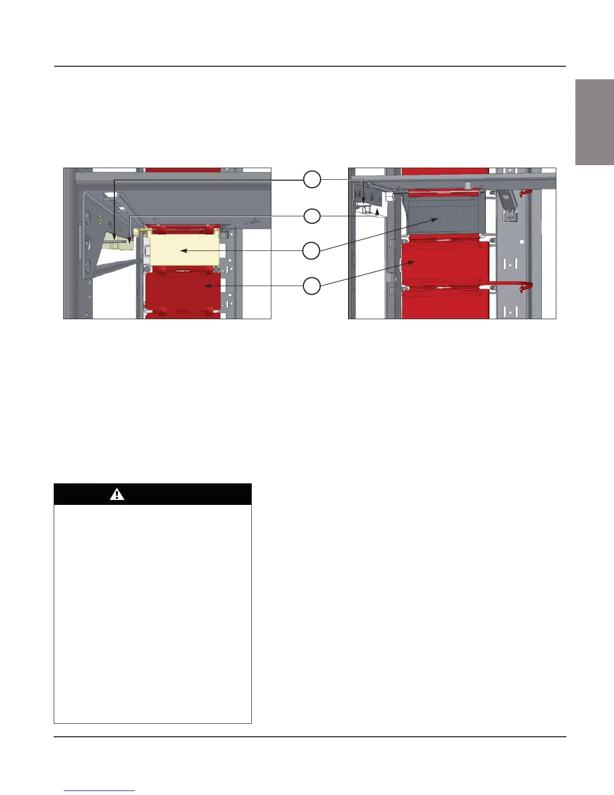
3. Vertical Bus Door and Clip: Provides a barrier against incidental
contact with the MCC vertical bus.
4. Manual Shutter: Prevents access to the unused vertical bus openings. The
manual shutter is held in place by a built-in locking feature that holds the
shutter in the closed position during shipping, set-up, and daily operations.
Compare the field-installed midshelf to the two designs above. If the
field-installed midshelf matches Style 1, follow the installation and removal
instructions starting below. If the field-installed midshelf matches Style 2,
follow the instructions starting on 128.
NOTE: Arc-rated MCCs have a midshelf specifically designed for arc-rated
MCCs (Schneider Electric part no. 80466-007-50; see Figure 116 on page
95). This midshelf includes arc pressure relief flaps and must be used when
installing arc-rated MCC units to maintain the arc containment ratings.
Installation—Style 1
Follow these instructions to install the automatic vertical bus shutter
assembly (see Figure 148 on page 126) to an existing Style 1 midshelf:
1. Turn off all power supplying this equipment before working on or inside
the equipment, and follow lockout/tagout procedures. Always use a
properly rated voltage sensing device to confirm the power is off.
2. Position the midshelf (Figure 148, Item A on 126) in the appropriate area
of the structure.
3. Place the mounting foot (Item B) of the shelf into the mounting pan slots
(Item C). Secure the shelf on the left and right with flat head screws
(Detail A, Item D).
4. Install the hinge leaves (Detail A, Item E) and the door (Item F) into the
hinge slots (Item G), which are on the structure corner channel. Fasten
the hinge leaves to the structure corner channel using hex head screws
(Item H).
5. Install the fastener receptacles (Detail B, Item J) into the bracket slots
(Item K) and fasten with hex head screws (Item H).
6. Install the automatic bus shutter assembly by rotating the mechanism
housing upward to clear the front corner channel of the structure.
7. Slide the automatic shutter assembly upward so that it fits snugly to the
left edge of the midshelf.
Figure 146: Automatic Vertical Bus Shutter in an MCC (front view)
3
4
2
1
Style 1 Style 2
DANGER
HAZARD OF ELECTRIC SHOCK,
EXPLOSION, OR ARC FLASH
• Apply appropriate personal protective
equipment (PPE) and follow safe electrical
work practices. See NFPA 70E or
CSA Z462.
• This equipment must be installed and
serviced only by qualified electrical
personnel.
• Turn off all power supplying this equipment
before working on or inside.
• Always use a properly rated voltage sensing
device to confirm power is off.
• Replace all devices, doors, and covers
before turning on power to this equipment.
Failure to follow this instruction will result
in death or serious injury.