Model 6 Motor Control Centers 80459-641-01E
Section 4—Installing the MCC 10/2012
© 1999–2012 Schneider Electric All Rights Reserved40
ENGLISH
Splicing Power Bus in NEMA Type
3R Enclosures
This section describes how to splice the power bus of a NEMA Type 3R
enclosure (manufactured after February 1998) to the power bus of another
NEMA Type 3R section. Bus splicing material is not captive if the section is
equipped with offset bus. Refer to “Splicing Offset Horizontal Bus” on
page 45 for instructions for splicing offset power bus in NEMA Type 3R
enclosures.
To splice power bus, follow these steps.
1. Turn off all power supplying this equipment before working on or inside
the equipment, and follow lockout/tagout procedures. Always use a
properly rated voltage sensing device to confirm the power is off.
2. Remove the horizontal wireway covers and slide the horizontal bus
barriers to gain access to the captive splice connectors (see Figure 41).
See Appendix A—Removal and Installation of Horizontal Bus
Barrier Panels for the steps for removing horizontal bus barriers.
NOTE: On the integral splice assembly, located on the left side of each
phase bus, the number of bus links is one greater than the number of
horizontal bus bars. This creates a sandwich splice. The rear-most
splice link contains the captive nuts.
3. Remove the two left bolts from each splice assembly. Then loosen, but do
not remove, the two right bolts of each splice assembly (see Figure 42). If
the bus has optional 85,000 A bus bracing supplied (see Figure 43), also
loosen the center nut of each splice assembly.
NOTE: Do not remove the two right bolts or the center bolt (if applicable)
from the splice assemblies. Doing so will permit spacers to fall from the
splice assembly. If this occurs, re-assemble the splice bars and spacers
(if applicable) in the proper order before continuing.
DANGER
HAZARD OF ELECTRIC SHOCK, EXPLOSION, OR ARC FLASH
• Apply appropriate personal protective equipment (PPE) and follow safe
electrical work practices. See NFPA 70E or CSA Z462.
• This equipment must only be installed and serviced by qualified
electrical personnel.
• Turn off all power supplying this equipment before working on or inside
equipment.
• Always use a properly rated voltage sensing device to confirm power is off.
• Replace all devices, doors, and covers before turning on power to this
equipment.
Failure to follow this instruction will result in death or serious injury.
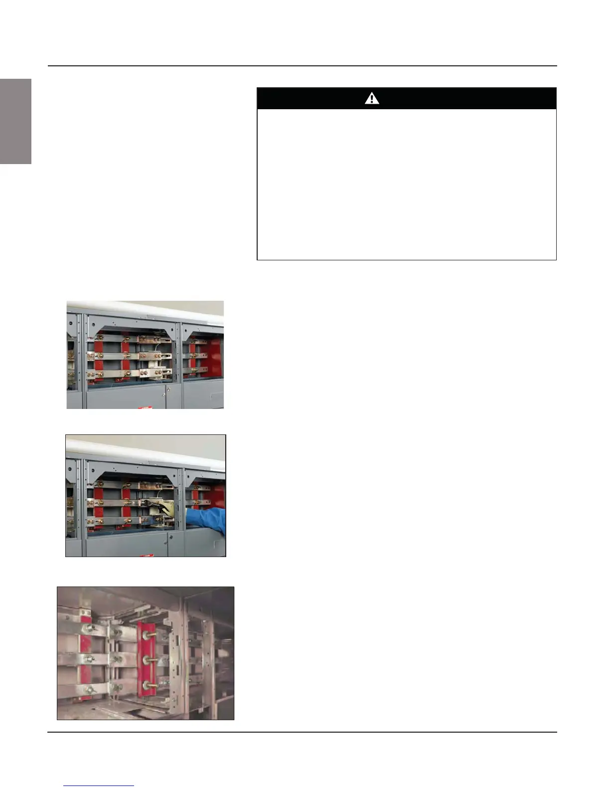
Figure 41: Wireway Covers Removed and
Horizontal Bus Barriers Open
Figure 42: Loosen Bolts
Figure 43: 85,000 A Bracing Option

 Loading...


