Model 6 Motor Control Centers 80459-641-01E
Section 6—Maintaining the MCC 10/2012
© 1999–2012 Schneider Electric All Rights Reserved62
ENGLISH
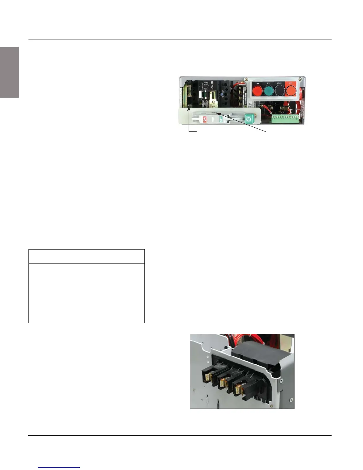
8. Grasp the operator handle flange and press down on the structure
interlock release (see Figure 87).
9. Firmly pull the unit forward to disengage the power stabs from the
vertical bus. The unit should now slide freely from the MCC structure.
10. The operator mechanism-to-structure interlock prevents the control unit
from being inserted or withdrawn with the handle in the ON position.
11. If the withdrawn unit is left in the structure, use appropriate lock-out/tag-
out procedures to avoid re-loading by non-authorized personnel.
12. Remove the control unit from the structure and place it on a flat surface
for servicing.
NOTE: Partial disassembly of the unit may be necessary to gain access
to various electrical connections for servicing.
Tests and Maintenance Performed
with the Control Unit Removed
Once the control unit is removed, perform the following tests and
maintenance:
Stab Assemblies—Inspect the stab assemblies (see Figure 88) for signs of
arcing or overheating. Replace the disconnect assembly (FA/KA type
circuit breakers) or the jaw connector assembly (H- or J-frame circuit
breakers) immediately if overheating has occurred. For replacement
disconnect assemblies, see “Section 13—Circuit Breaker and Fusible
Switch Replacement” beginning on page 111.
NOTE: If the stab assembly is badly pitted, the vertical bus may also need
to be replaced.
Figure 87: Operator Handle and Interlock Release
Operator handle flang
Structure interlock release
NOTIC
HAZARD OF EQUIPMENT DAMAGE
Do not remove the protective lubricant from the
stabs. If additional lubricant is required, order
Schneider Electric electrical joint compound
#PJC-7201.
Failure to follow this instruction can result
in equipment damage.
Figure 88: Stab Assembly