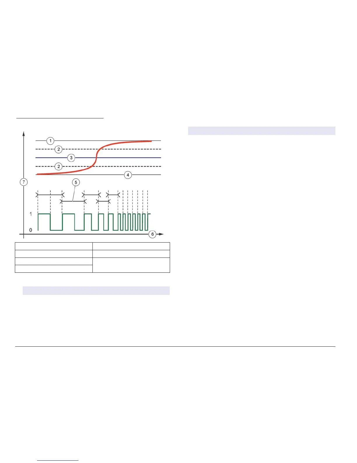
Figure 25 Frequency control function
1 High limit 5 Cycle duration
2 Deadband 6 Time (x-axis)
3 Setpoint 7 Selected source (y-axis)
4 Low limit
• Warning Function
Option Description
Warning Sets the level for warning activation. Refer to the sensor manual
for the numbers for individual warning messages.
Display setup
Configures the controller display.
1. From the Settings menu, select sc200 Setup and push ENTER.
2. Select Display Setup and push ENTER.
Option Description
Adjust
Order
View and modify the measurement display order.
• See Current Order—View the current display order
• Add Measurements—Add selected measurements to the
display
• Remove Measurements—Remove selected
measurements from the display
• Reorder List—Select one or more measurements and
change their order in the display
• See Default Order—View the default display order
• Set to Default—Set the display order to the default
configuration
1ote SoPe of tKe aEove Zill not Ee availaEle if no adMustPent
is possiEle for tKat option e.g. 5eorder /ist and 5emove
0easurements Zill not Ee availaEle if only one PeasurePent
is selected for display.
Display
Contrast
Adjust the contrast to a value between the minimum of +1 and
the maximum of +9
Edit Name Assigns a name to the controller
Update the date and time
1. From the Settings menu, select sc200 Setup and push ENTER.
2. Select Set Date/Time and push ENTER.
3. Select Date Format from the Set Date/Time screen and push
ENTER.
4. Select a format and push ENTER.
5. Select Date/Time from the Set Date/Time screen and push ENTER.
6. Update the entries.
a. Use the right and left arrow keys to highlight a field.
b. Use the up and down arrow keys to change the values in the field
and push ENTER.
36 (nglisK