80459-641-01E Model 6 Motor Control Centers
10/2012 Section 8—Mag-Gard™ and PowerPact™ Motor Circuit Protector Settings
© 1999–2012 Schneider Electric All Rights Reserved
73
ENGLISH
Section 8—Mag-Gard™ and
PowerPact™ Motor Circuit
Protector Settings
The National Electrical Code
®
(NEC
®
) and Canadian Electrical Code (CEC)
require that magnetic starters, used in combination with adjustable magnetic
trip-only circuit breakers, have an overload relay in each conductor.
Mag-Gard or PowerPact Motor Circuit Protectors are the standard motor
circuit protectors used in Model 6 MCCs.
Adjusting Mag-Gard or PowerPact
Magnetic Trip Setting
The adjustable magnetic trip setting is factory-set at Lo for Mag-Gard Motor
Circuit Protectors. For PowerPact H- and J-frame Motor Circuit Protectors,
the Full Load Amp Setting (FLA) is factory set to the lowest position and the
instantaneous trip setting (Im) is factory set to the Auto 1 position. For
PowerPact P-frame Motor Circuit Protectors (ET1.0M electronic trip unit),
the adjustable instantaneous trip setting is factory set to its lowest position.
These settings may have to be adjusted for proper motor start-up. For both
Mag-Gard and PowerPact Motor Circuit Protectors, refer to the magnetic
trip set-point limits outlined in the applicable national installation codes. For
PowerPact H- and J-frame Motor Circuit Protectors, refer also to the
PowerPact Motor Circuit Protector Settings instruction bulletin
(48940-260-01) shipped with the equipment.
To access the Mag-Gard trip adjustment dial:
1. Turn off all power supplying this equipment before working on or inside
the equipment, and follow lockout/tagout procedures. Always use a
properly rated voltage sensing device to confirm the power is off.
2. Place the unit handle in the OFF position and open the door.
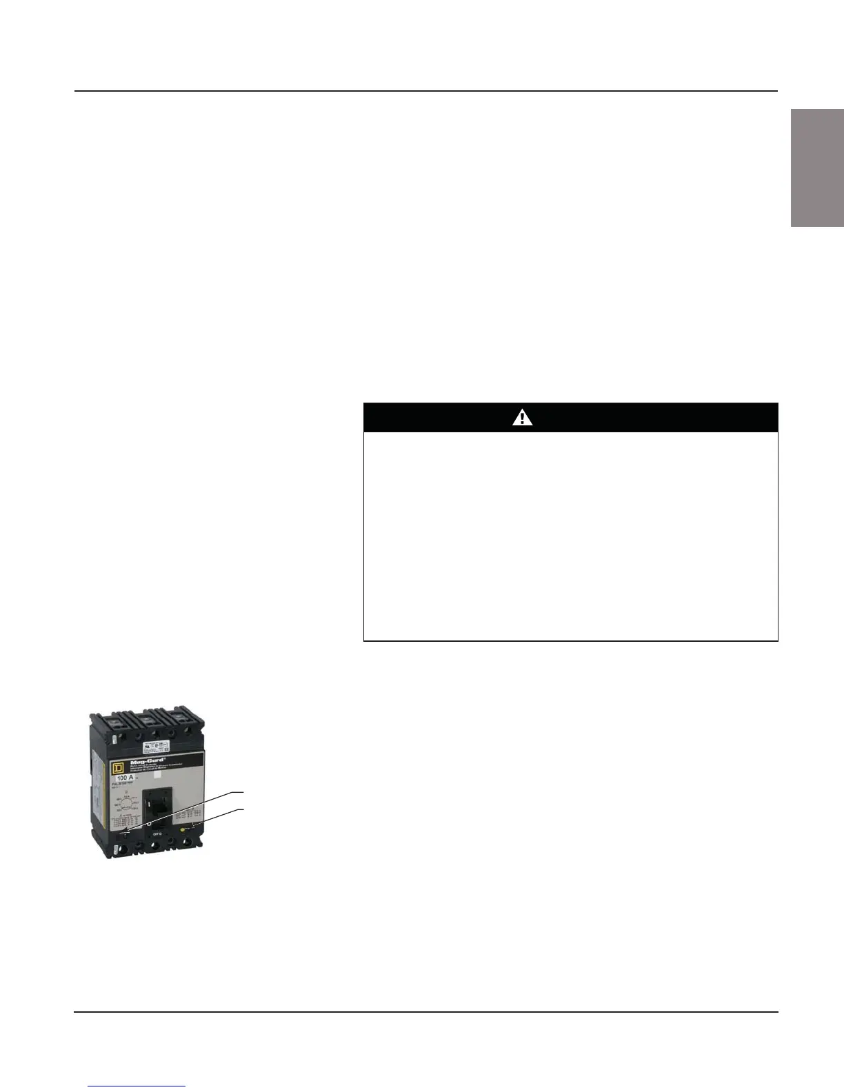
3. While pushing the door interlock lever forward, trip the circuit breaker by
pressing the yellow test button (see Figure 104). The disconnect handle
will automatically move up, allowing access to the adjustment dial.
After obtaining the motor full load current from the motor nameplate, select
an adjustable trip setpoint to test start the motor. Further adjustments may
be required because of motor load characteristics. Refer to applicable
national installation codes for permissible setpoints.
After adjusting the trip setting, reset the circuit breaker by moving the
disconnect handle to the ON position and then to the OFF position.
DANGER
HAZARD OF ELECTRIC SHOCK, EXPLOSION, OR ARC FLASH
• Apply appropriate personal protective equipment (PPE) and follow safe
electrical work practices. See NFPA 70E or CSA Z462.
• This equipment must only be installed and serviced by qualified
electrical personnel.
• Turn off all power supplying this equipment before working on or inside
equipment.
• Always use a properly rated voltage sensing device to confirm power is off.
• Replace all devices, doors, and covers before turning on power to this
equipment.
Failure to follow this instruction will result in death or serious injury.
Figure 104: Mag-Gard Magnetic Trip
Adjustment
Trip adjustment dial
Test button