Model 6 Motor Control Centers 80459-641-01E
Appendix A—Removal and Installation of Horizontal Bus Barrier Panels 10/2012
© 1999–2012 Schneider Electric All Rights Reserved114
ENGLISH
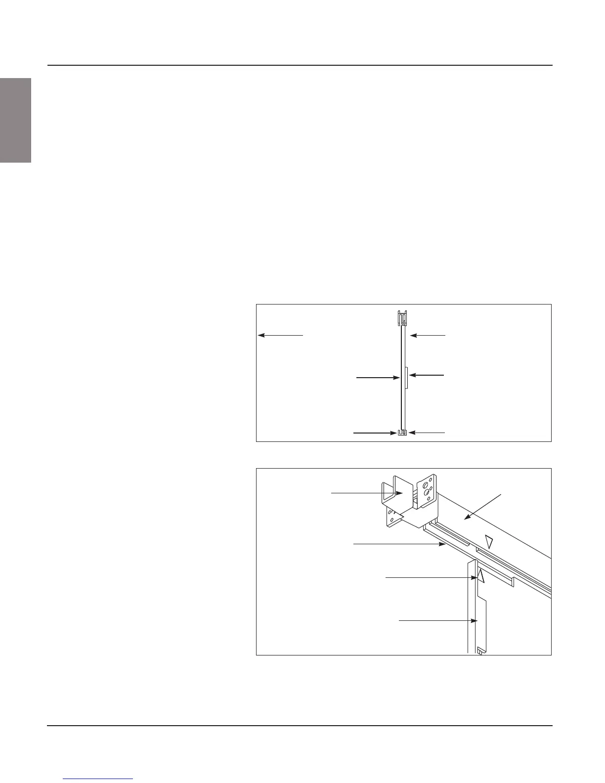
Installation NOTE: The horizontal bus barrier contains two identical panels with arrows
at the top. The “handle” on the left panel faces the front of the MCC section.
The “handle cavity” on the right panel faces the front of the MCC section
(see Figure 130).
1. Turn off all power supplying this equipment before working on or inside
the equipment, and follow lockout/tagout procedures. Always use a
properly rated voltage sensing device to confirm the power is off.
2. Align the arrows on the right panel and top track as shown in Figure 131.
3. Lift the panel up into the rear groove of the top track.
4. Lower the panel into the rear groove of the bottom track.
5. Slide the panel to the far right.
6. Align the arrows on the left panel and top track.
7. Repeat Steps 3 and 4 using the left panel and front groove.
8. Slide the panel to the left until it locks (snaps) into place.
9. Verify that the barrier is completely closed by making sure that the wiring
compartment is isolated from the bus compartment.
Figure 130: Right Panel (Side View)
Figure 131: Installing the Right Panel into the Rear Groove
Wireway Area
Horizontal Bus Area
Horizontal bus barrier -
right panel
Handle
Rear groove
Front of section
Handle cavity
Front groove
Right panel
Snap
Top track
Endcap
Rear groove
Flange points away from MCC