Model 6 Motor Control Centers 80459-641-01E
Section 4—Installing the MCC 10/2012
© 1999–2012 Schneider Electric All Rights Reserved50
ENGLISH
Crimp Lug Cable Assembly for
Cabled Disconnect Unit
Installation
1. Turn off all power supplying this equipment before working on or inside
the equipment, and follow lockout/tagout procedures. Always use a
properly rated voltage sensing device to confirm the power is off.
2. Access the horizontal bus in the motor control center.
3. Remove the horizontal bus mounting nuts and washers (item
➄) from
the horizontal bus assembly.
4. Insert the loom bolts (item
➁) through the rear of the lug pad (item ➂).
5. Using the mounting nuts and washers from Step 3, attach the lug pad to
the horizontal bus mounting bolts (item ➀).
6. Torque the horizontal bus mounting nuts to 820–840 lb-in (93–95 N•m).
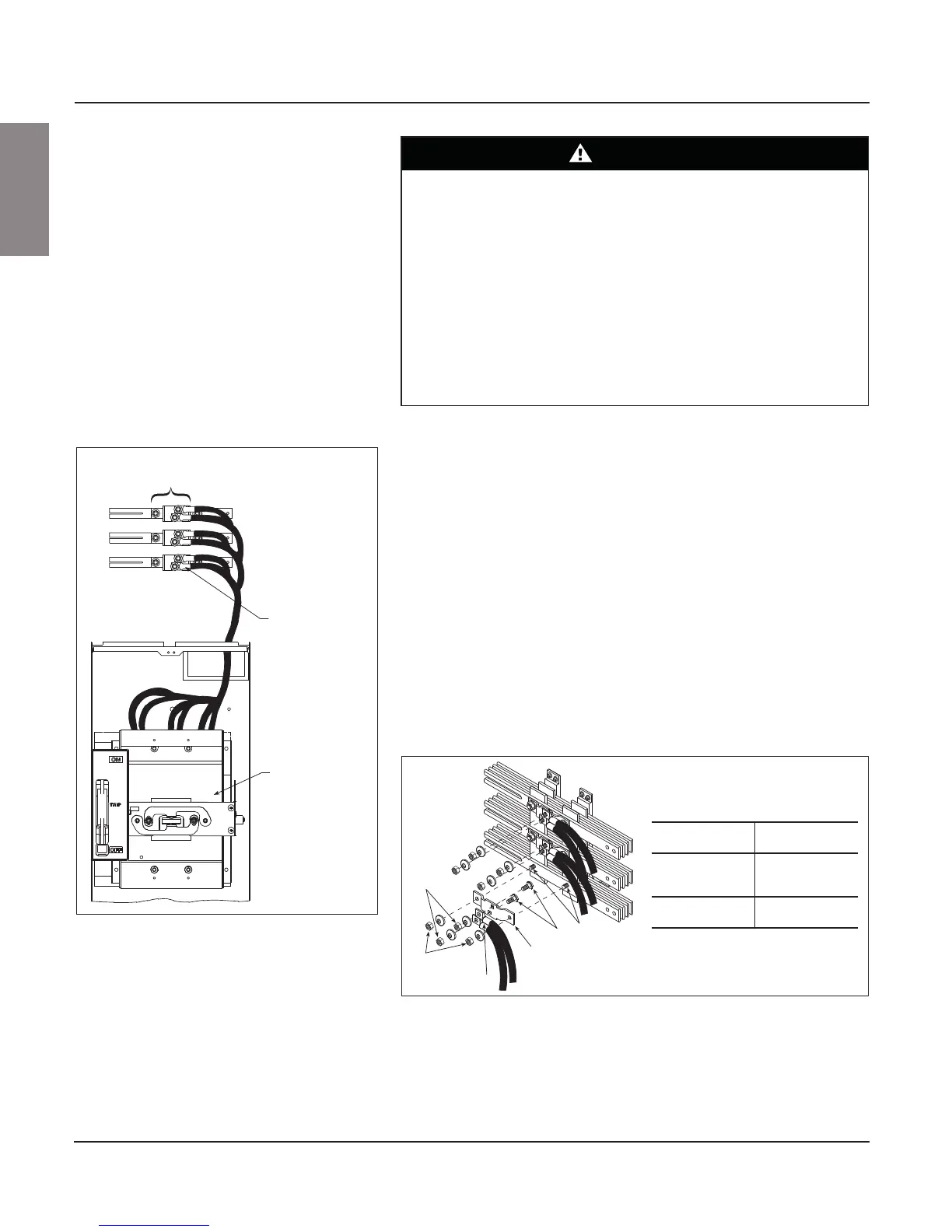
7. Route the cable to the circuit breaker or fuse disconnect unit (see
Figure 64); trim cable length as required.
8. Using the lug pad nuts and washers (item
➅), attach the crimp lug cable
assembly (item
➃) to the loom bolts on the lug pad.
9. Torque the lug pad nuts to 820–840 lb-in (93–95 N•m).
DANGER
HAZARD OF ELECTRIC SHOCK, EXPLOSION, OR ARC FLASH
• Apply appropriate personal protective equipment (PPE) and follow safe
electrical work practices. See NFPA 70E or CSA Z462.
• This equipment must only be installed and serviced by qualified
electrical personnel.
• Turn off all power supplying this equipment before working on or inside
equipment.
• Always use a properly rated voltage sensing device to confirm power is off.
• Replace all devices, doors, and covers before turning on power to this
equipment.
Failure to follow this instruction will result in death or serious injury.
Figure 64: Typical Cabled Disconnect Unit
Typical cabled
disconnect unit
(circuit breaker or
fusible switch)
Crimp lug cable
assembly (one or
two per phase)
Horizontal bus
mounting assembly
Figure 65: Typical Horizontal Bus Assembly
➀
➁
➂
➃
➅
➄
➀ Horizontal bus
mounting bolts
➃ Crimp lug cable
assembly
➁ Loom bolts ➄Horizontal bus
mounting nuts
and washers
➂ Lug pad ➅ Lug pad nuts and
washers