37
Section 7 Troubleshooting
7.1 Error Codes
When a sensor is experiencing an error condition, the sensor reading on
the measurement screen will flash and all relays and analog outputs associated with the
sensor will be held. The following conditions will cause the sensor reading to flash:
• Sensor calibration
• Relay timer washing cycle
• Loss of communication
Highlight the Sensor Diag menu and press
ENTER. Highlight Errors and press ENTER to
determine the cause of the error.
Errors are defined in Table 6.
7.2 Warnings
A sensor warning will leave all menus, relays, and outputs functioning normally, but will
cause a warning icon to flash on the right side of the display. Highlight the Sensor Diag
menu and press
ENTER to determine the cause of the warning.
A warning may be used to trigger a relay and users can set warning levels to define the
severity of the warning. Errors are defined in Table 7.
Table 6 Error Codes
Displayed Error Definition Resolution
ADC FAILURE System measurement fails Contact Technical Consulting Services.
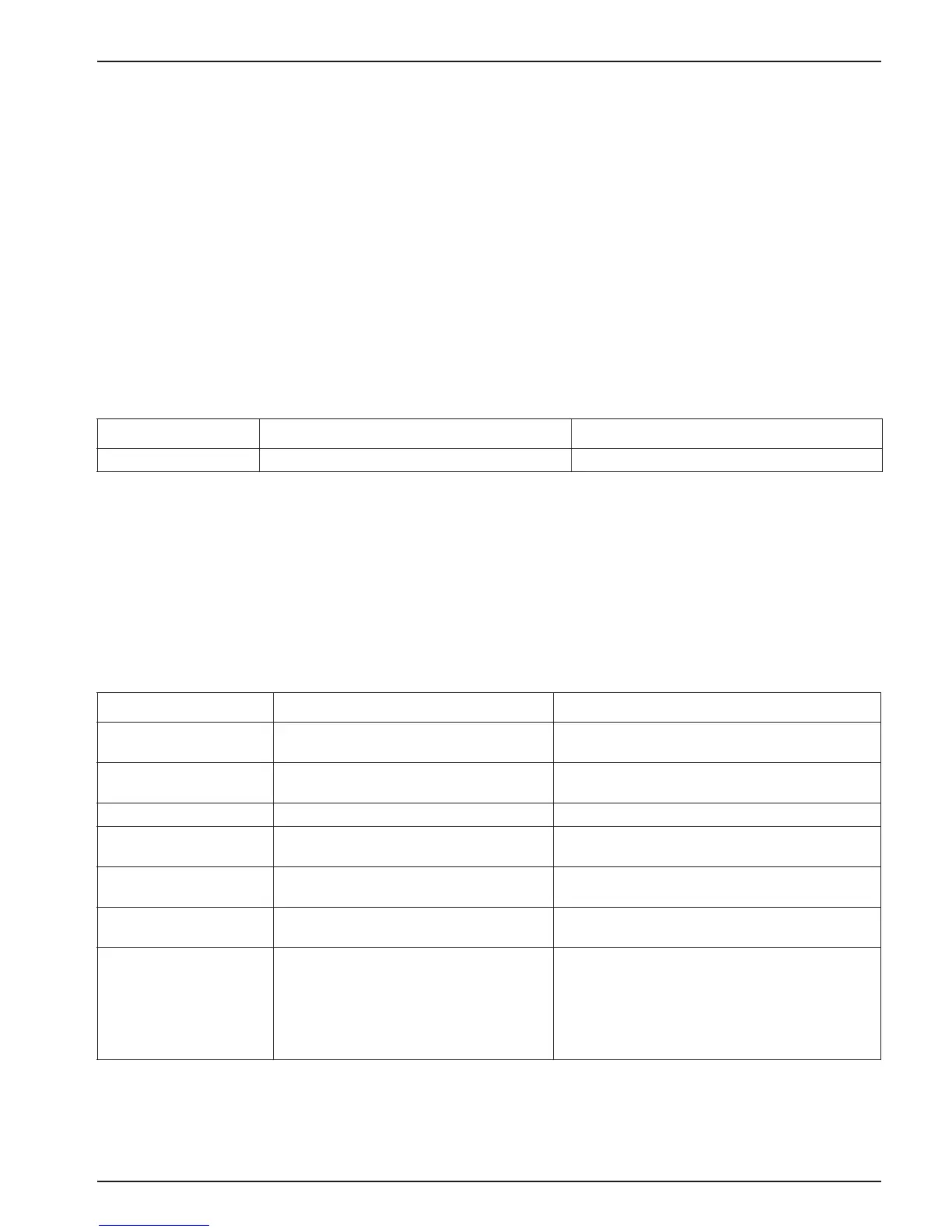
Table 7 Warning Codes
Displayed Warning Definition Resolution
PROBE OUT RANGE
Measured pH/ORP exceeds the expected
value range.
Contact Technical Consulting Services.
TEMP OUT RANGE
Measured temperature exceeds the
expected value range.
Contact Technical Consulting Services.
FLASH FAILURE System flash memory write has failed. Contact Technical Consulting Services.
ACTIVE. ELEC
Standard electrode is not performing within
the required specifications.
Contact Technical Consulting Services.
REF. ELECTRODE
Reference electrode is not performing
within the required specifications.
Contact Technical Consulting Services.
CAL REQUIRED
60 days has elapsed since the last
calibration
Perform a calibration.
REPLACE SENSOR
One year has elapsed since the sensor has
been installed.
Clean the sensor and replace the salt bridge and
standard cell solution (see section 6.2 on page 34
and section 6.2.1 on page 35). Reset the counter
in the SENSOR SETUP>CONFIGURE>
SENSOR DAYS menu.
If necessary, replace the sensor.