Model 6 Motor Control Centers 80459-641-01E
Section 4—Installing the MCC 10/2012
© 1999–2012 Schneider Electric All Rights Reserved38
ENGLISH
Power Bus Splicing MCCs with Multiple
Bar/Phase Splice Kit
NOTE: On the integral splice assembly, located on the left side of each
phase bus, the number of bus links is one greater than the number of
horizontal bus bars. This creates a sandwich splice. The rear-most
splice link contains the captive nuts.
1. Remove the two left bolts. Loosen, but do not remove, the two right bolts
on the splice assembly (see Figure 36).
NOTE: Do not remove the two right bolts from the splice assemblies.
Doing so will permit spacers to fall from the splice assembly. If this
occurs, re-assemble the splice bars and spacers (if applicable) in the
proper order before continuing.
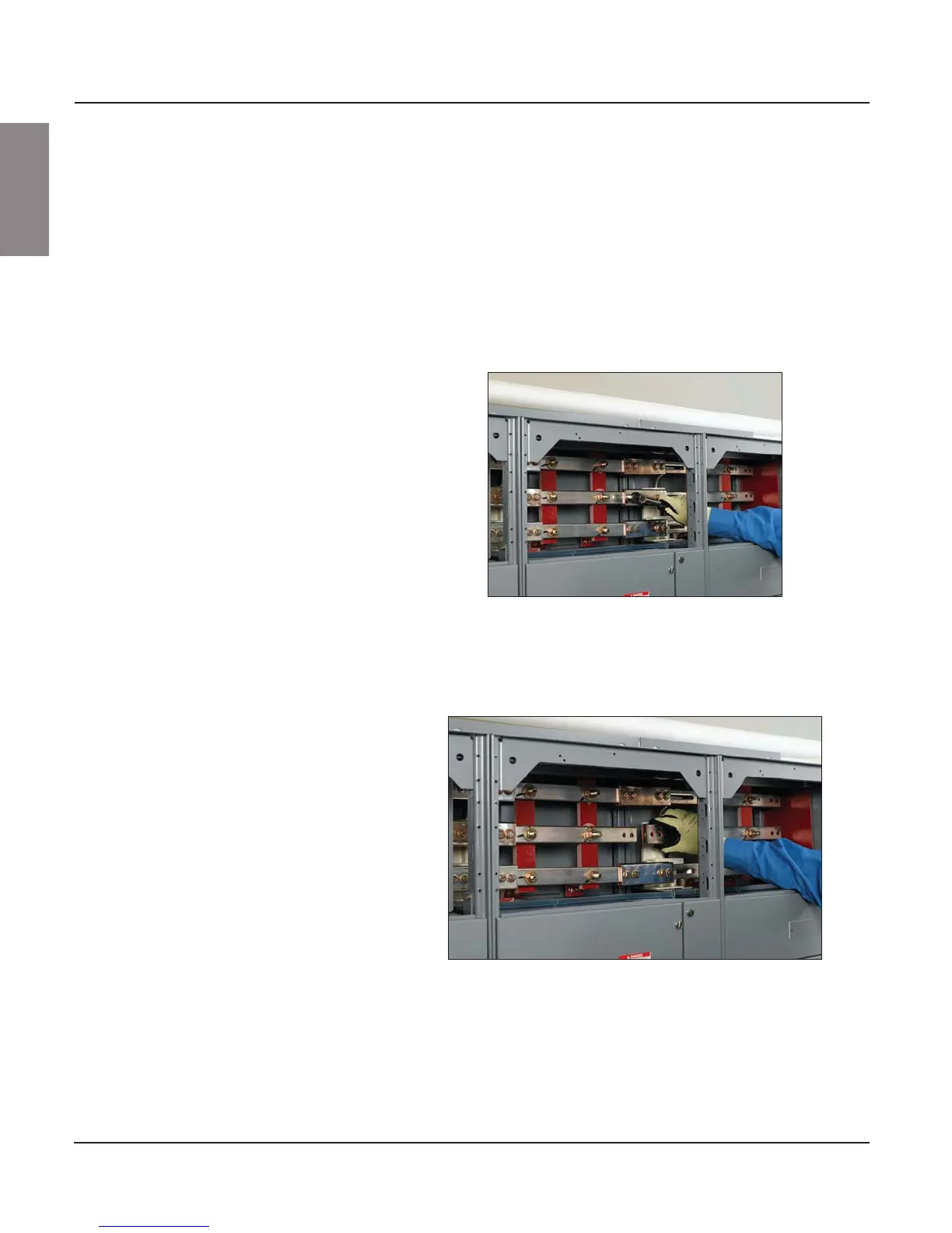
2. Slide the splice assembly to the left until the two left holes are in line
with the corresponding holes in the horizontal bus on the left section
(see Figure 37).
Figure 36: Removing the Left Bolts and Loosening the Right Bolts
on the Splice Assembly
Figure 37: Aligning the Splice and Bus Holes